Space Shuttle Vehicle
SPACE SHUTTLE ORBITER
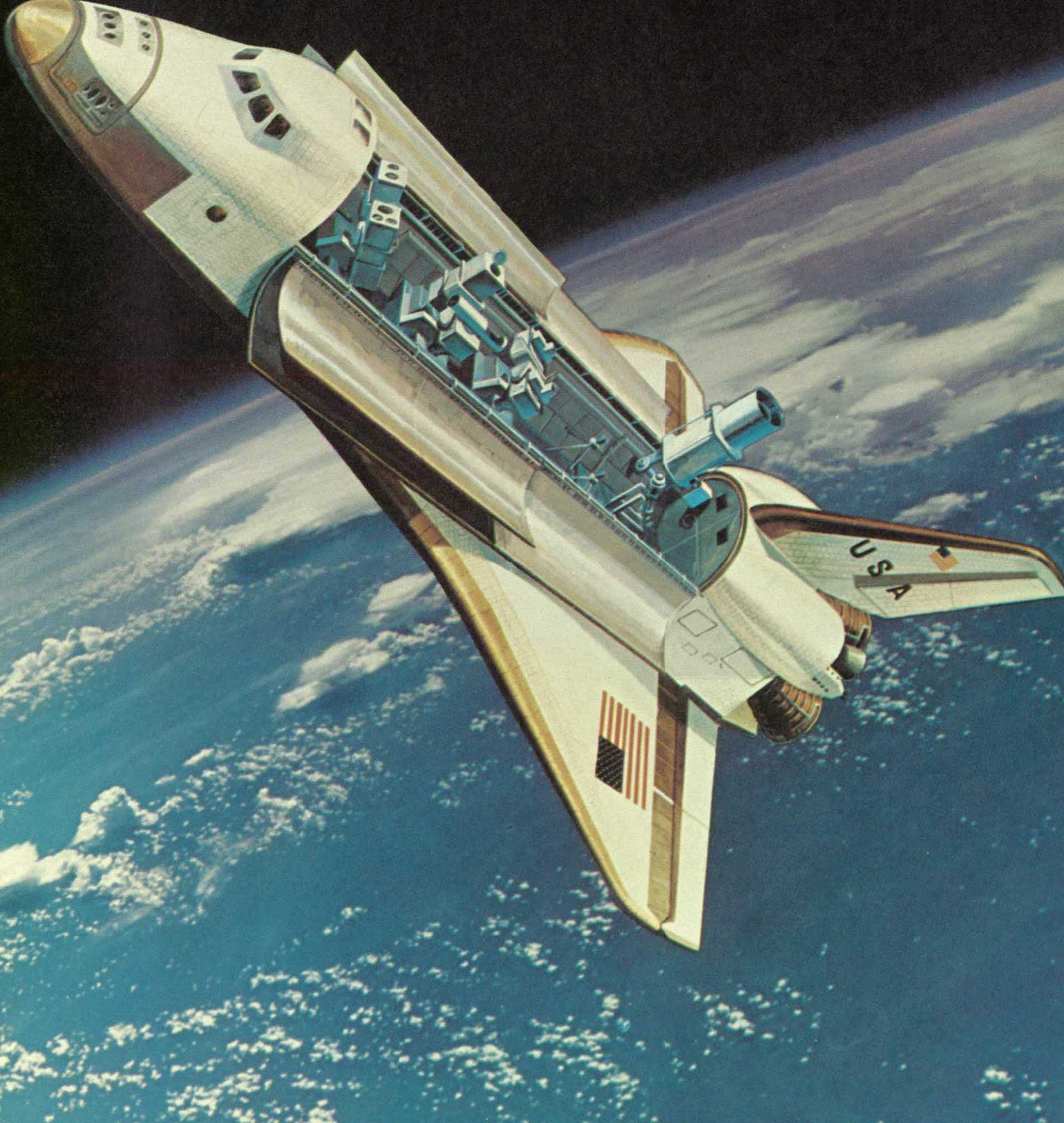
The Orbiter spacecraft contains the crew and payload for the Space Shuttle system. The Orbiter can deliver to orbit payloads of 29,500 kilograms (65,000 pounds) with lengths to 18 meters (60 feet) and diameters of 5 meters (15 feet). The orbiter is comparable in size and weight to modern transport aircraft; it has a dry weight of approximately 68,000 kilograms (150,000 pounds), a length of 37 meters (122 feet), and a wingspan of 24 meters (78 feet).
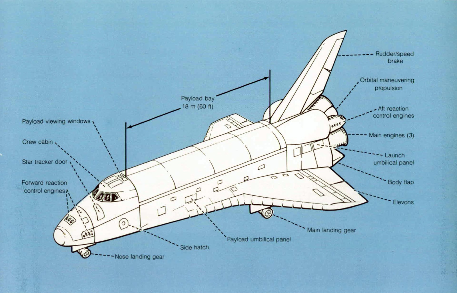
The crew compartment can accommodate seven crewmembers and passengers for some missions but will hold as many as 10 persons in emergency operations.
The three main propulsion rocket engines used during launch are contained in the aft fuselage. The rocket engine propellant is contained in the external tank (ET), which is jettisoned before initial orbit insertion. The orbital maneuvering subsystem (OMS) is contained in two external pods on the aft fuselage. These units provide thrust for orbit insertion, orbit change, rendezvous, and return to Earth. The reaction control subsystem (RCS) is contained in the two OMS pods and in a module in the nose section of the forward fuselage. These units provide attitude control in space and precision velocity changes for the final phases of rendezvous and docking or orbit modification. In addition, the RCS, in conjunction with the Orbiter aerodynamic control surfaces, provides attitude control during reentry. They take effect in the lower, more dense atmosphere providing control of the Orbiter at speeds less than Mach 5. The Orbiter is designed to land at a speed of 95 msec (185 knots), similar to current high-performance aircraft.
EXTERNAL TANK
The external tank contains the propellants for the Orbiter main engines: liquid hydrogen (LH2) fuel and liquid oxygen (LO2) oxidizer. All fluid controls and valves (except the vent valves) for operation of the main propulsion system are located in the Orbiter to minimize throwaway costs. Antivortex and slosh baffles are mounted in the oxidizer tank to minimize liquid residuals and to damp fluid motion. Five lines (three for fuel and two for oxidizer) interface between the external tank and the Orbiter. All are insulated except the oxidizer pressurization line. Liquid level point sensors are used in both tanks for loading control.
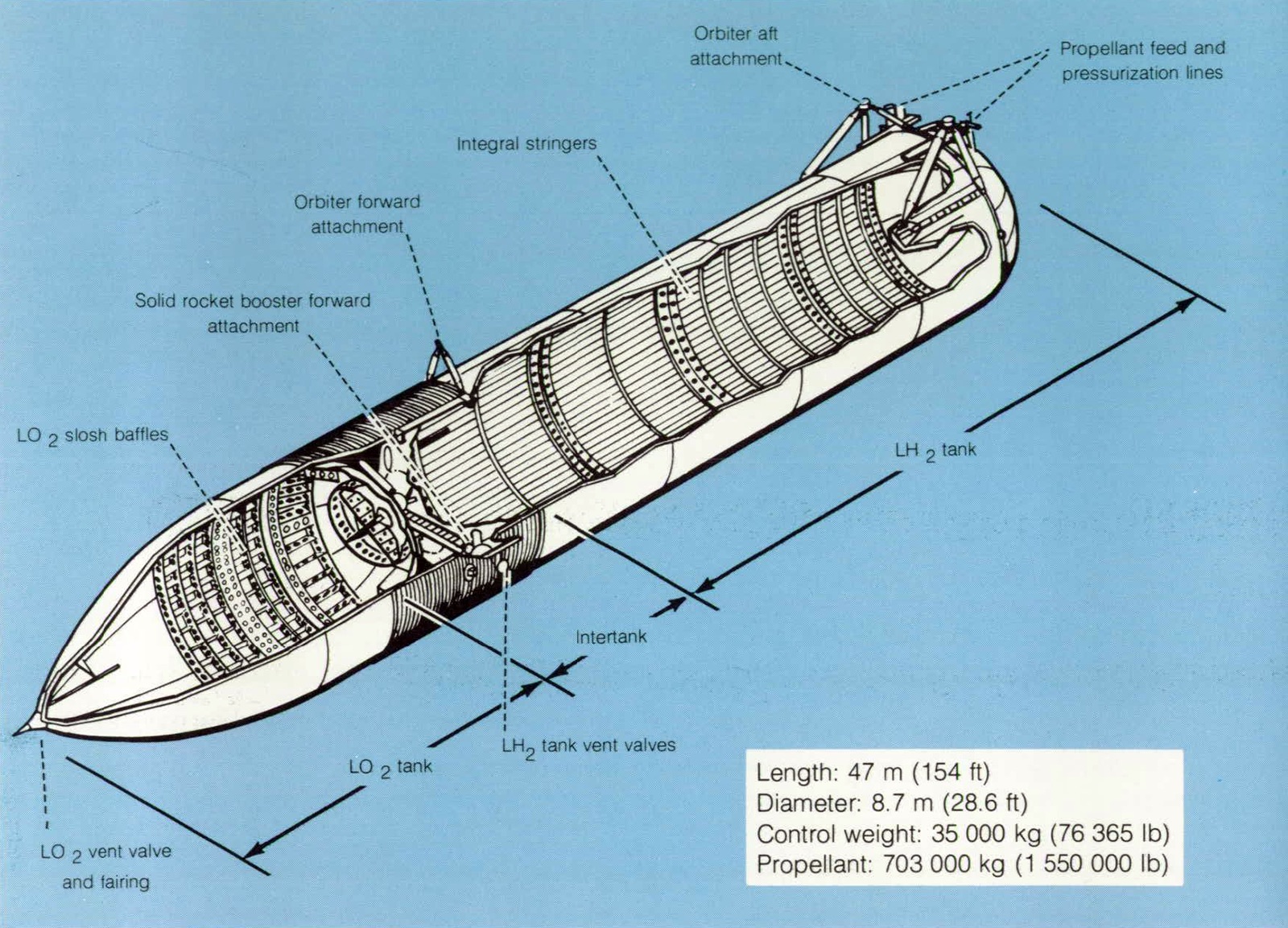
- Length: 47 m (154 ft)
- Diameter: 8.7 m (28.6 ft)
- Control weight: 35,000 kg (76,365 lb)
- Propellant: 703,000 kg (1,550,000 lb)
At lift-off, the external tank contains 703,000 kilograms (1,550,000 pounds) of usable propellant. The LH2 tank volume is 1523 m3 (53,800 ft3) and the LO2 tank volume is 552 m3 (19,500 ft3). These volumes include a 3-percent ullage provision. The hydrogen tank is pressurized to a range of 220,600 to 234,400 N/m2 (32 to 34 psia) and the oxygen tank to 137,900 to 151,700 N/m2 (20 to 22 psia).
Both tanks are constructed of aluminum alloy skins with support or stability frames as required. The sidewalls and end bulkheads use the largest available width of plate stock. The skins are butt-fusion-welded together to provide reliable sealed joints. The skirt aluminum structure uses skin/stringers with stabilizing frames.
Spray-on foam insulation (SOFI) is applied to the complete outer surface of the external tank, including the sidewalls and the forward bulkheads. This spray-on ablator is applied to all protuberances, such as attachment structures. because shock impingement causes increased heating to these areas. The thermal protection system (TPS) coverage is minimized by using the heat-sink approach provided by the sidewalls and propellants.
SOLID ROCKET BOOSTERS
Two solid rocket boosters (SRB’s) burn for 2 minutes with the main propulsion system of the Orbiter to provide initial ascent thrust. Primary elements of the booster are the motor, including case, propellant, igniter. and nozzle: forward and aft structures: separation and recovery avionics: and thrust vector control subsystems Each SRB weighs approximately 583,600 kilograms (1,286,600 pounds) and produces 11,800,000 newtons (2,650,000 pounds) of thrust at sea level. The propellant grain is shaped to reduce thrust approximately one-third 55 seconds after lift-off to prevent overstressing the vehicle during the period of maximum dynamic pressure. The thrust vector control subsystem has a maximum omniaxial gimbal capability of slightly over 7° which, in conjunction with the Orbiter main engines, provides flight control during the Shuttle boost phase

Dimensions
- Length: 4547 cm (1790 in.)
- Diameter: 371 cm (146 in.)
Approximate Weights and Thrust (Each)
- Gross weight: 583,600 kg (1,286,600 lb)
- Inert weight: 81,900 kg (180,500 lb)
- Thrust (sea level): 11,800,000 N (2,650,000 lb)
The SRB is attached to the tank at the forward end of the forward skirt by a single thrust attachment. The pilot, drogue, and main parachute risers of the recovery subsystem are attached to the same thrust structure.
The SRB’s are released by pyrotechnic separation devices at the forward thrust attachment and the aft sway braces. Eight separation rockets on each SRB (four aft and four forward) separate the SRB from the Orbiter and external tank. They continue through a 67,000-meter (220,000-foot) apogee, then at 5800 meters (19,000 feet) the SRB nose cap is deployed for recovery initiation. The pilot chute deploys the drogue chute, which, after stabilizing the SRB, then deploys the aft frustrum with the main parachute packs. The three main chutes inflate to a reefed condition at 2700 meters (8800 feet) and are fully extended at 1000 meters (3400 feet). When the SRB impacts the water approximately 300 kilometers (160 nautical miles) downrange, the parachutes are jettisoned and the tow pendant deployed. The recovery ship deploys a nozzle plug which is inserted in the SRB to facilitate inflation and dewatering so that the booster will float on the surface horizontally for towing to port for refurbishing and subsequent reuse.
ORBITER MAIN PROPULSION
The Orbiter main propulsion engines burn for approximately 8 minutes. For the first 2 minutes, the engines of the main propulsion system burn in parallel with the SRB motors. These two systems provide the velocity increment necessary to almost achieve the initial mission orbit. The final boost into the desired orbit is provided by the orbital maneuvering system.
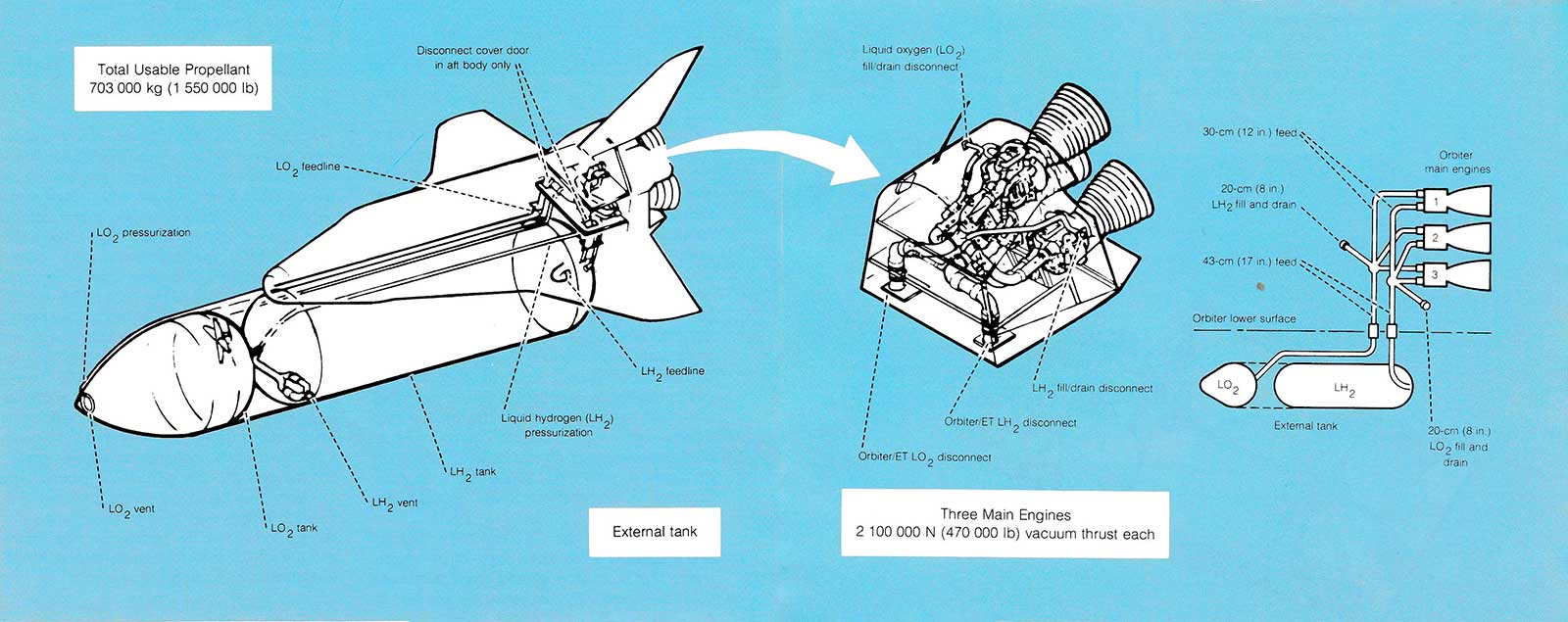
- Total Usable Propellant: 703,000 kg (1,550,000 lb)
- Three Main Engines: 2,100,000 N (470,000 lb) vacuum thrust each
Each of the three main engines is approximately 4.3 meters (14 feet) long with a nozzle almost 2.4 meters (8 feet) in diameter, and each produces a nominal sea-level thrust of 1,668,100 newtons (375,000 pounds) and a vacuum thrust of 2,100,000 newtons (470,000 pounds). The engines are throttleable over a thrust range of 50 to 109 percent of the nominal thrust level, so Shuttle acceleration can be limited to 3g. The engines are capable of being gimbaled for flight control during the Orbiter boost phase.
The 603,300 kilograms (1,134,000 pounds) of liquid oxygen and 99,800 kilograms (226,000 pounds) of liquid hydrogen used during ascent are stored in the external tank. The propellant is expended before achieving orbit and the tank falls to the ocean after separating from the Orbiter. The fluid lines interface with the external tank through disconnects located at the bottom of the Orbiter aft fuselage. The hydrogen disconnects are mounted on a carrier plate on the left side of the Orbiter and the oxygen disconnects on the right side. These disconnect openings are covered by large doors immediately after tank separation from the Orbiter. Ground servicing is done through umbilicals on both sides of the aft fuselage.
ORBITER REACTION CONTROL SUBSYSTEM
The reaction control subsystem (RCS) has 38 bipropellant primary thrusters and 6 vernier thrusters to provide attitude control and threeaxis translation during the orbit insertion, on-orbit, and reentry phases of flight The RCS consists of three propulsion modules, one in the forward fuselage and one in each of the aft propulsion pods All modules are used for external tank separation. orbit insertion, and orbital maneuvers. Only the aft RCS modules are used for reentry attitude control
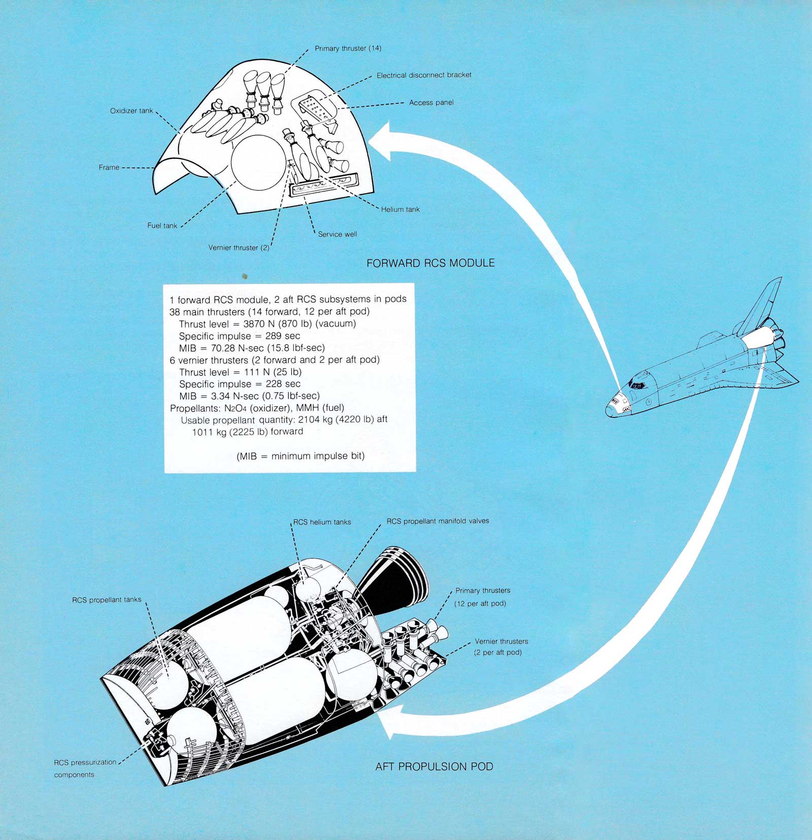
1 forward RCS module, 2 aft RCS subsystems in pods
38 main thrusters (14 forward, 12 per aft pod)
Thrust level = 3870 N (870 lb) (vacuum)
Soecific impulse = 289 sec
MIB = 70.28 N-sec (15.8 lbf-sec)
6 vernier thrusters (2 forward and 2 per aft pod)
Thrust level = 111 N (25 lb)
Specific impulse = 228 sec
MIB = 3.34 N-sec (0.75 lbf-sec)
Propellants: N2O4 (oxidizer), MMH (fuel)
Usable propellant quantity: 2104 kg (4220 lb) aft
1011 kg (2225 lb) forward
(MIB = minimum impulse bit)
The RCS propellants are nitrogen tetroxide (N2O4) as the oxidizer and monomethylhydrazine (MMH) as the fuel. The design mixture ratio of 1.61 (oxidizer weight to fuel weight) was set to permit the use of identical propellant tanks for both fuel and oxidizer. The capacity of each propellant tank in each module is 675 kilograms (1488 pounds) ofN2O4 and 422 kilograms (930 pounds) of MMH. The usable propellant quantity for each location is 622 kilograms (1369 pounds) of N2O4 and 389 kilograms (856 pounds) of MMH in the nose section module and 1321 kilograms (2905 pounds) N2O 4and 825 kilograms (1,815 pounds) in both aft section modules,
ORBITAL MANEUVERING SUBSYSTEM
After external tank separation, the orbital maneuvering subsystem (OMS) provides the thrust to perform orbit insertion, orbit circularization, orbit transfer, rendezvous, and deorbit. The integral OMS tankage is sized to provide propellant capacity for a change in velocity of 305 m/sec (1000 ft/sec) when the vehicle carries a payload of 29,500 kilograms (65,000 pounds). A portion of this velocity change capacity is used during ascent. The 10,852 kilograms (23,876 pounds) of maximum deliverable propellant is contained in two pods, one on each side of the aft fuselage. Each pod contains a high-pressure helium storage bottle; tank pressurization regulators (4) and controls; a fuel tank; an oxidizer tank; and a pressurefed regeneratively cooled rocket engine. Each engine produces a vacuum thrust of 26,700 newtons (6000 pounds) at a chamber pressure of 861,850 N/m2(125 psia) and a specific impulse of 313 seconds.
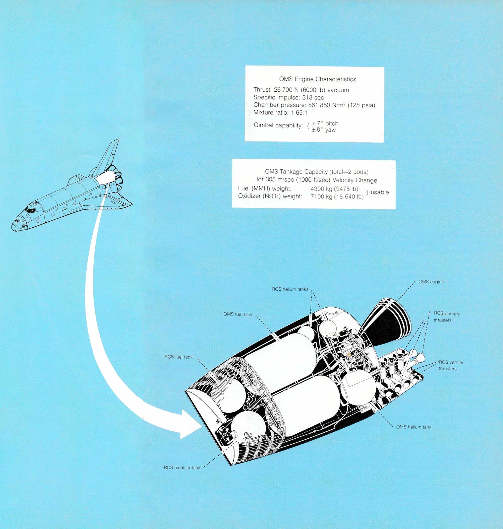
OMS Engine Characteristics
- Thrust: 26,700 N (6000 lb) vacuum
- Specific impulse: 313 sec
- Chamber pressure: 861,850 N/m2 (125 psia)
- Mixture ratio: 1.65:1
- Gimbal capability: ±7° pitch , ±8° yaw
OMS Tankage Capacity (total-2 pods) for 305 m/sec (1000 ft/sec) Velocity Change
- Fuel (MMH) weight: 4300 kg (9475 lb) [usable]
- Oxidizer (N2O4) weight: 7100 kg (15,640 lb) [usable]
The OMS and RCS propellant lines are interconnected (1) to supply propellant from the OMS tanks to the ACS thrusters on orbit and (2) to provide crossfeed between the left and right OMS and RCS systems. In addition, propellant lines from the auxiliary OMS tanks in the Orbiter cargo bay (if carried as a mission kit) interconnect with the OMS propellant lines in each pod.
ORBITER STRUCTURE SUBSYSTEM
The Orbiter structure is constructed primarily of aluminum protected by reusable surface insulation The primary structural subassemblies are the crew module and forward fuselage, midfuselage and payload bay doors, aft fuselage and engine thrust structure, wing, and vertical tail.
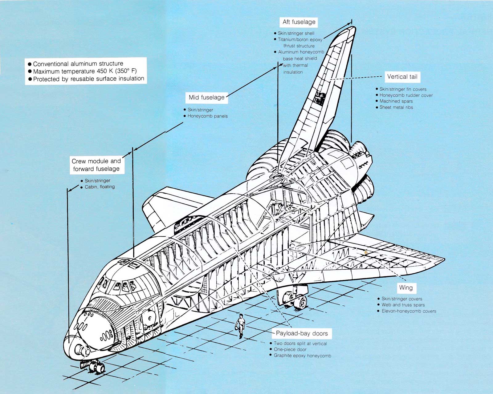
- Conventional aluminum structure
- Maximum temperature 450 K (350° F)
- Protected by reusable surface insulation
Crew module and forward fuselage
- Skin/stringer
- Cabin, floating
Mid fuselage
- Skin/stringer
- Honeycomb panels
Aft fuselage
- Skin/stringer shell
- Titanium/boron epoxy thrust structure
- Aluminum honeycomb base heat shield with thermal insulation
Vertical tail
- Skin/stringer fin covers
- Honeycomb rudder cover
- Machined spars
- Sheet metal ribs
Wing
- Skin/stringer covers
- Web and truss spars
- Elevon-honeycomb covers
Payload-bay doors
- Two doors solit at vertical
- One-piece door
- Graphite epoxy honeycomb
The crew module is machined aluminum alloy plate with integral stiffening stringers. The module has a side hatch for normal ingress and egress, a hatch into the airlock from the crew living deck, and a hatch from the airlock into the payload bay. The forward fuselage structure is aluminum alloy skin/stringer panels, frames, and bulkheads. The window frames are machined parts attached to the structural panels and frames.
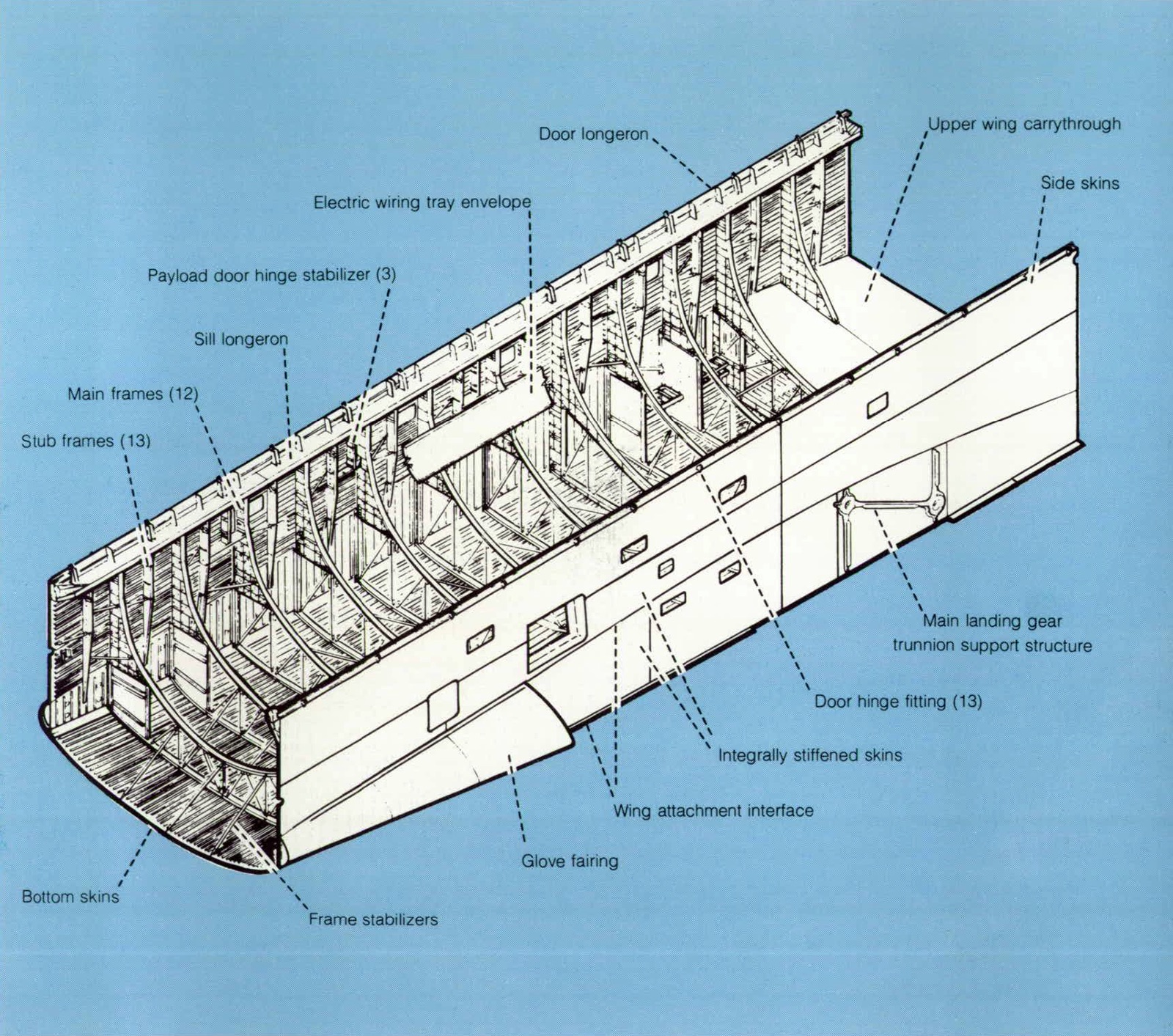
The midfuselage is the primary load-carrying structure between the forward and aft fuselage; it also includes the wing carrythrough structure and payload-bay doors. The frames are constructed as a combination of aluminum panels with riveted or machined integral stiffeners and a truss structure center section. The upper half of the midfuselage consists of structural payload bay doors, hinged along the side and split at the top centerline. The doors are made of graphite epoxy honeycomb material.
The main engine thrust loads to the midfuselage and external tank are carried by the aft fuselage structure. This structure is an aluminum integral machined panel and includes a truss-type internal titanium structure reinforced with boron epoxy. A honeycomb base aluminum heat shield with insulation at the rear protects the main engine systems.
The wing is constructed with corrugated spar web, truss-type ribs, and riveted skin/stringer covers of aluminum alloy. The elevons are constructed of aluminum honeycomb.
The vertical tail is a two-spar, multirib, stiffened-skin box assembly of aluminum alloy. The tail is bolted to the aft fuselage at the two main spars. The rudder/speed brake assembly is divided into upper and lower sections.
ORBITER THERMAL PROTECTION SYSTEM
The thermal protection subsystem includes those materials which are installed on the outer surface of the vehicle to protect it from the high temperatures generated during launch and entry back into the atmosphere from orbit. The peak heating rates and the longest exposure to these rates occur during entry when equilibrium surface temperatures may range from 1925 K (3000° F) at stagnation points on the nose and leading edges of the wing and tail down to about 590 K (600° F) on leeward surfaces. The TPS is composed of two types of reusable surface insulation (RSI) tiles, a high temperature structure coupled with internal insulation, thermal window panes, coated Nomex felt, and thermal seals to protect against aerodynamic heating.
| Insulation | Area, m2 (ft2) | Weight, kg (lb) | ||
|---|---|---|---|---|
| FRSI | 304.2 | (3,275) | 357 | (788) |
| LRSI | 281.7 | (3,032) | 845 | (1,862) |
| HRSI | 475.4 | (5,117) | 3812 | (8,403) |
| RCC | 37.9 | (409) | 1371 | (3,023) |
| Misca | -- | 643 | (1,418) | |
| Total | 1099.2 | (11,833) | 7028 | (15,494) |
aIncludes bulk insulation, thermal barriers, and closeouts
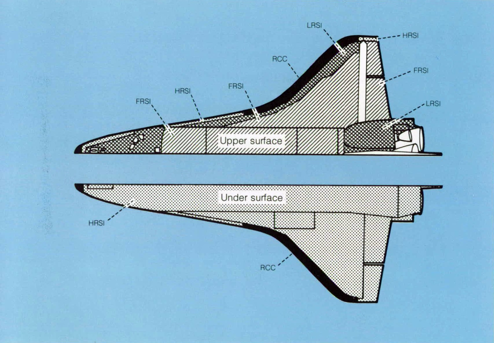
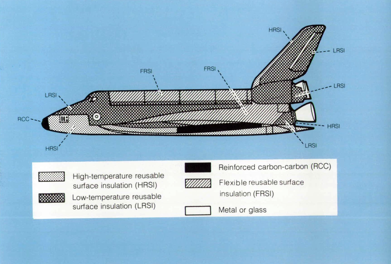
The RSI tiles covering the Orbiter are made of coated silica fiber. The two types of RSI tiles differ only in surface coating to provide protec-tion for different temperature regimes. The low temperature reusable surface insulation (LRSI) consists of 20-centimeter (8-inch) square silica tiles and covers the top of the vehicle where temperatures are less than 925 K (1200° F). The high-temperature reusable surface insulation (HRSI) is 15-centimeter (6-inch) square silica tiles and covers the bottom and some leading edges of the Orbiter where temperatures are below 1500 K (2300° F). A high-temperature structure of reinforced carbon-carbon (RCC) is used with internal insulation for the nose cap and wing leading edges where temperatures are greater than 1500 K (2300° F) Flexible reusable surface insulation (FRSI) consisting of coated Nomex felt is used on the upper cargo-bay door, lower aft fuselage sides, and upper aft wing where temperatures are less than 645 K (700° F).
PAYLOAD ACCOMMODATIONS
The Orbiter systems are being designed to handle various payloads and to support a variety of payload functions. The payload and mission stations on the flight deck provide command and control facilities for payload operations required by the cognizant scientist (the user). Remote-control techniques can be employed from the ground when desirable. The Spacelab payload provides additional command and data management capability plus a work area in the payload bay for the payload specialists. The crew will be able to go into the space environment for Orbiter or payload servicing, deployment, repair, retrieval or inspection tasks, or the crew can use a manipulator to handle complete payloads or selected packages.
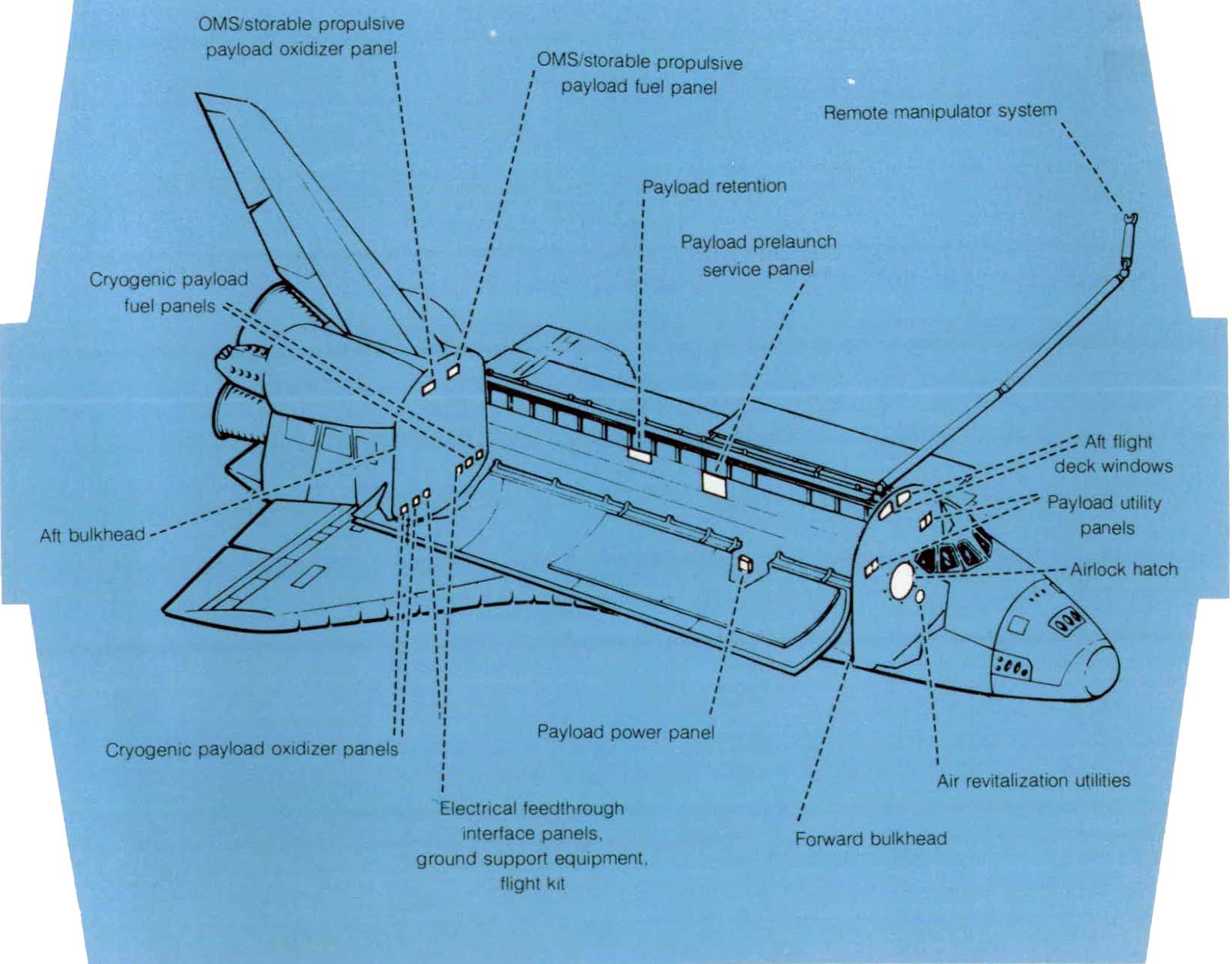
The manipulator arm, complemented by the television display system, allows the payload operator to transfer experiment packages and cargo in and out of the Orbiter bay, to place into orbit spacecraft carried up by the Shuttle, and to inspect retrieved orbital spacecraft. The system can also aid in inspection of critical areas on the vehicle exterior, such as the heat shield.
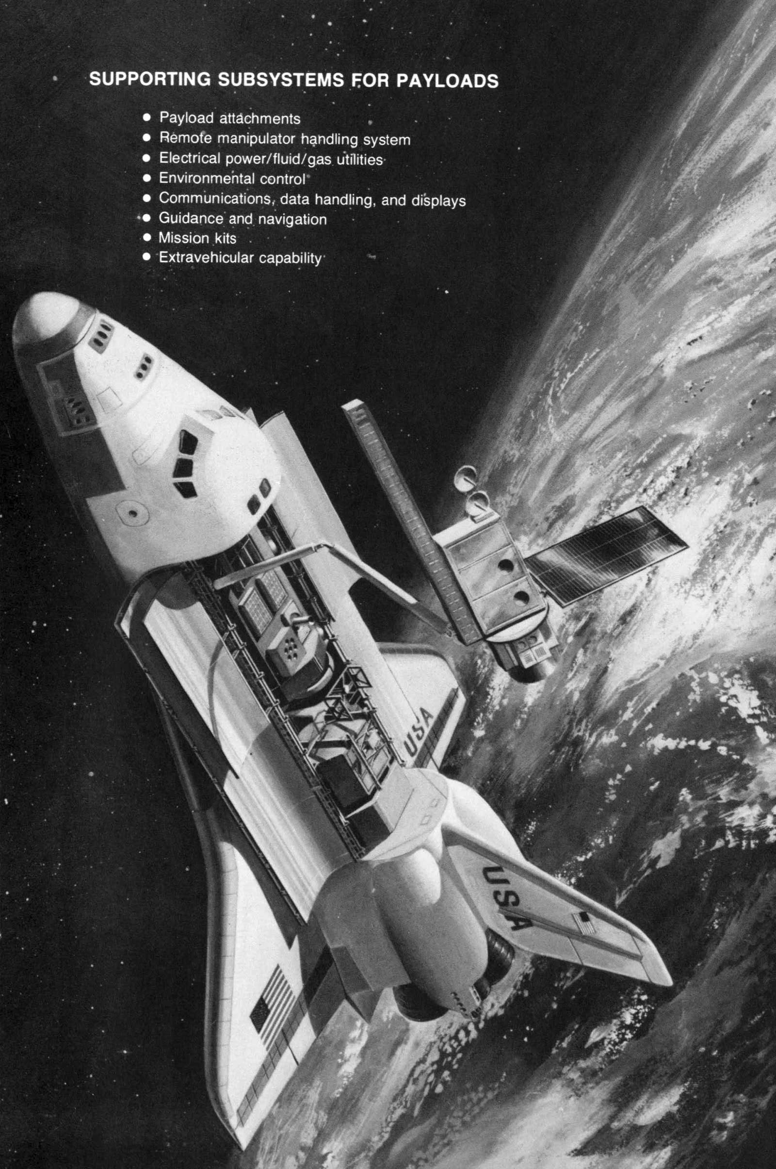
SUPPORTING SUBSYSTEMS FOR PAYLOADS
- Payload attachments
- Remote manipulator handling system
- Electrical power/fluid/gas utilities
- Environmental control
- Communications, data handling, and displays
- Guidance and navigation
- Mission kits
- Extravehicular capability
PAYLOAD HANDLING—INTERNATIONAL COOPERATION
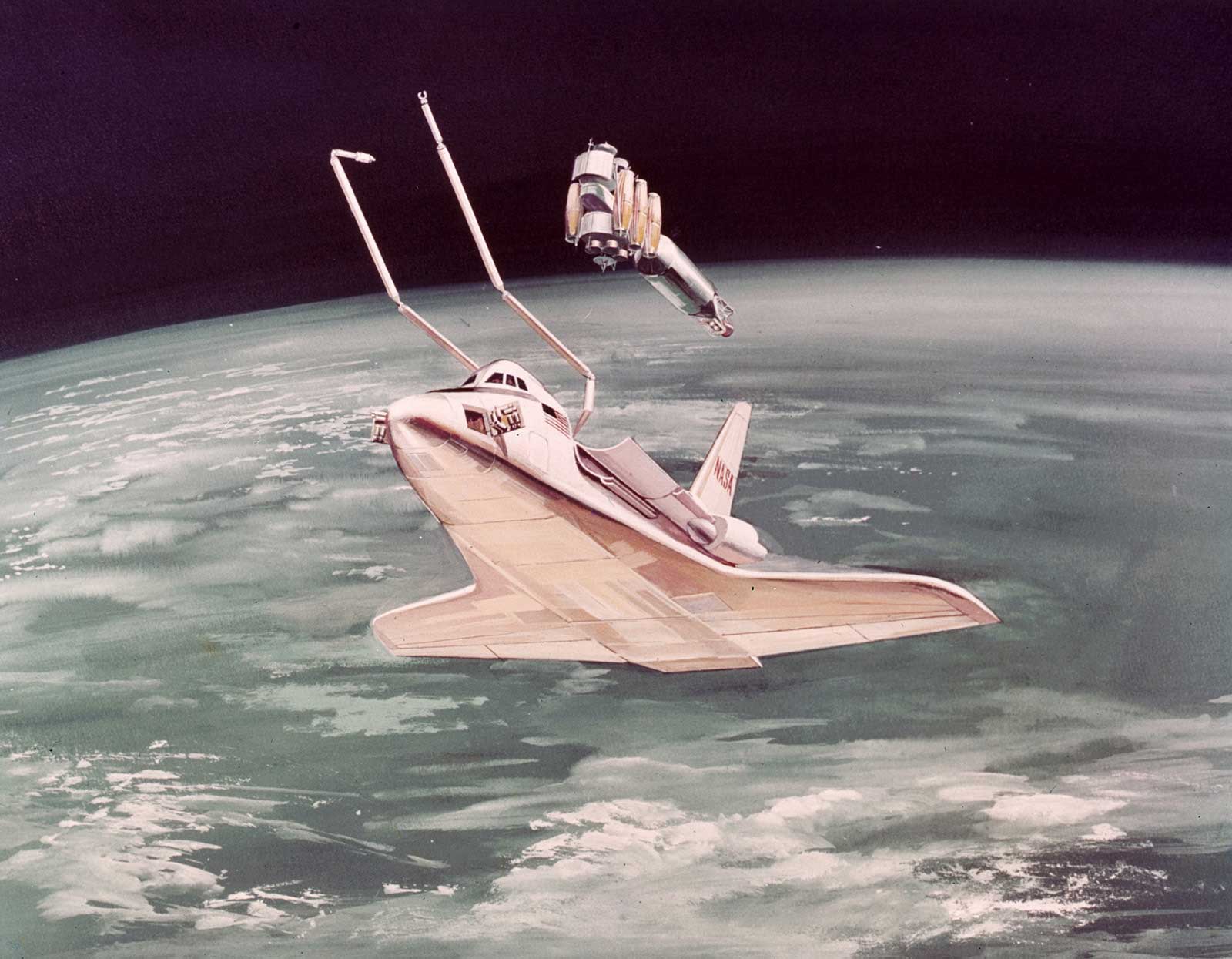
The deployment and retrieval of payloads are accomplished by using the general purpose remote manipulator system. Payload retrieval Involves the combined operations of rendezvous, stationkeeping and manipulator arm control. One manipulator arm is standard equipment on the Orbiter and may be mounted on either the left or right longeron. A second arm can be installed and controlled separately for payloads requiring handling with two manipulators. Each arm has remotely controlled television and lights to provide side viewing and depth perception. Lights on booms and side walls provide appropriate illumination levels for any task that must be performed in the payload bay.
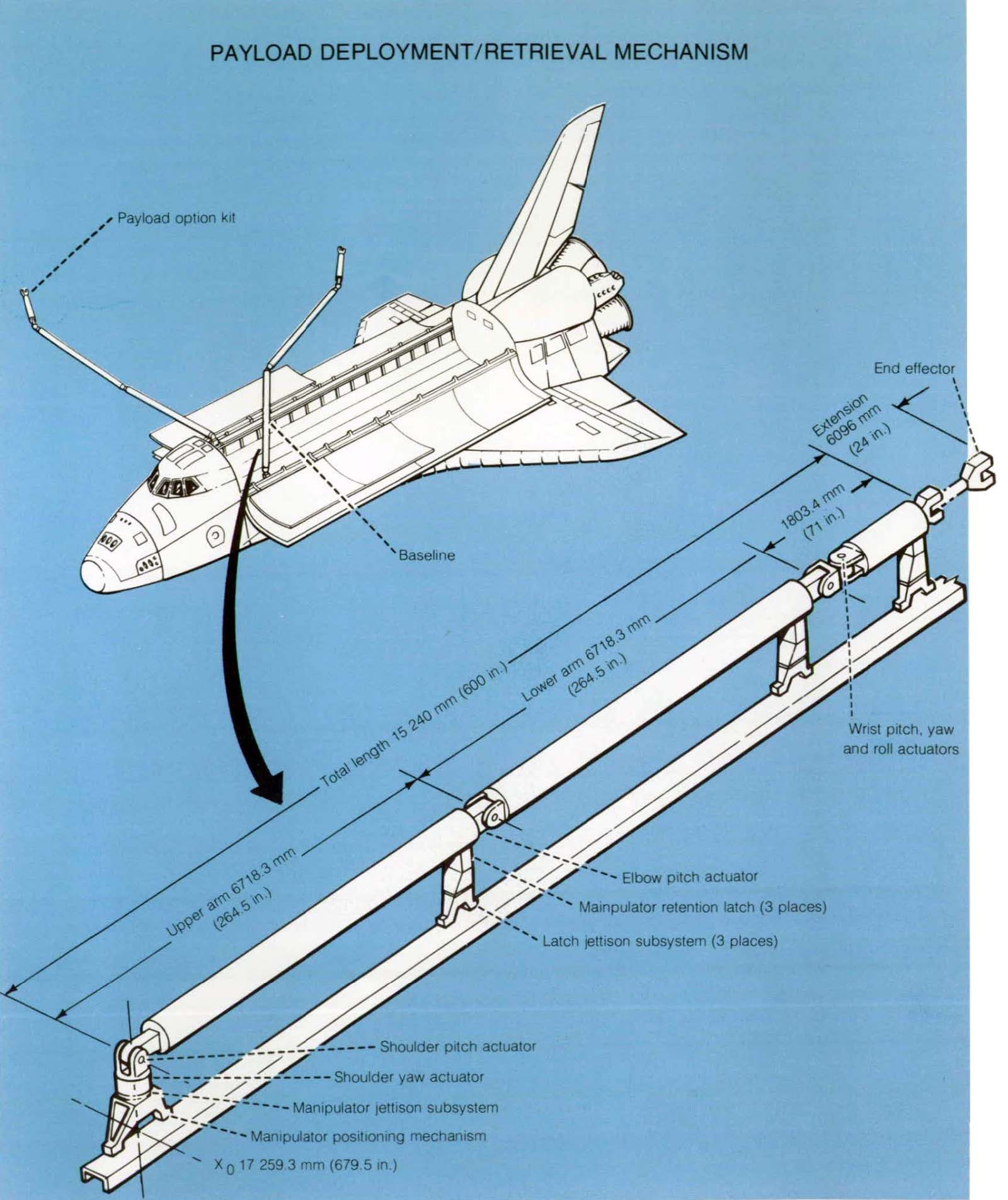
The remote manipulator system is being funded, designed, developed, and manufactured by a Canadian industrial team under the overall direction of the National Research Council of Canada.
CREW CABIN AND CREW ACCOMMODATIONS
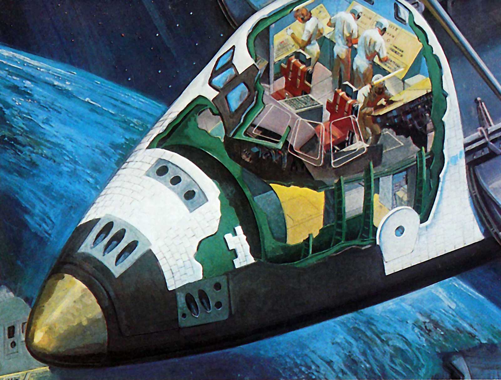
The Orbiter cabin is designed as a combination working and living area. The pressurized crew compartment has a large volume, 71.5 m3(2525 ft3), and contains three levels. The upper section, or flight deck, contains the displays and controls used to pilot, monitor, and control the Orbiter, the integrated Shuttle vehicle, and the mission payloads. Seating for as many as four crewmembers can be provided. The midsection contains passenger seating, the living area, an airlock, and avionics equipment compartments. An aft hatch in the airlock provides access to the cargo bay. The lower section contains the environmental control equipment and is readily accessible from above through removable floor panels.
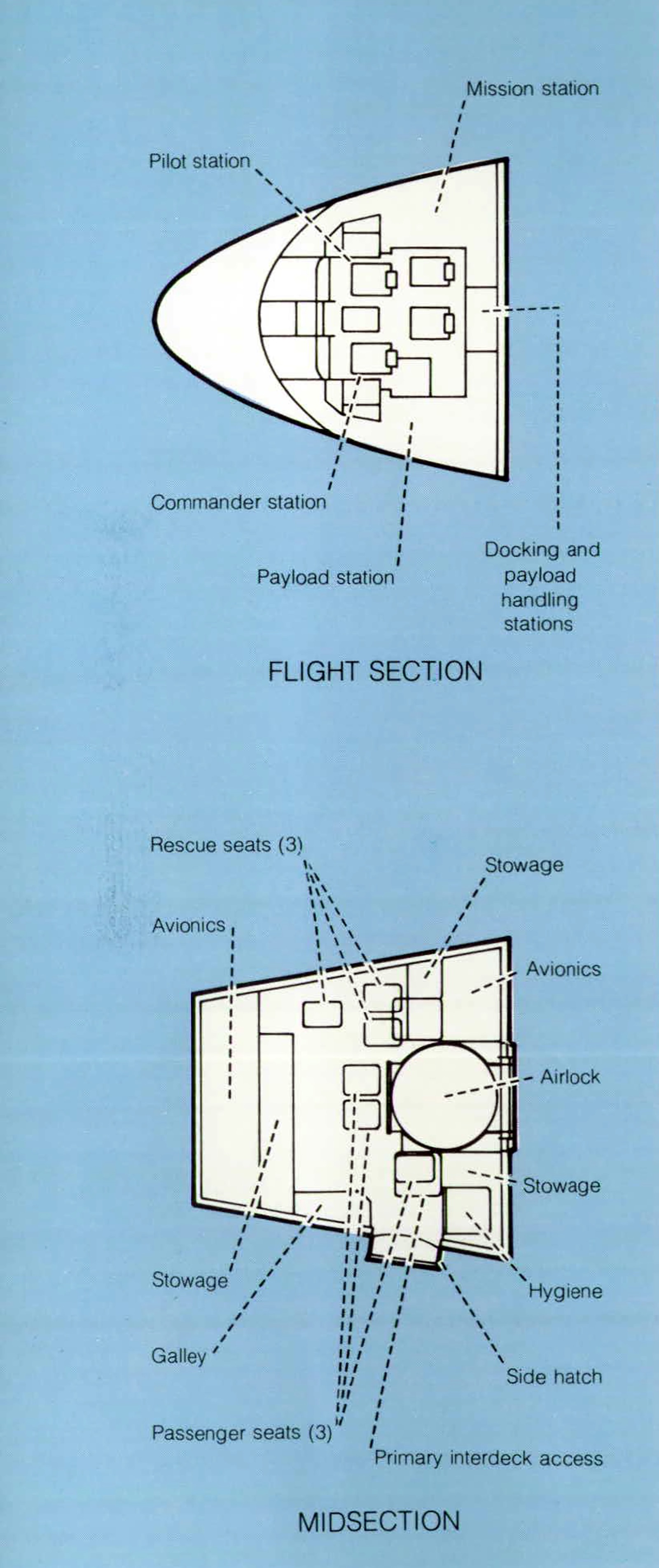
Flight deck displays and controls are organized into four functional areas: (1) two forward-facing primary flight stations for vehicle operations, (2) two aft-facing stations, one for payload handling and the other for docking, (3) a payload station for management and checkout of active payloads, and (4) a mission station for Orbiter subsystem/payload interface, power, and communications control in the remaining flight deck area.

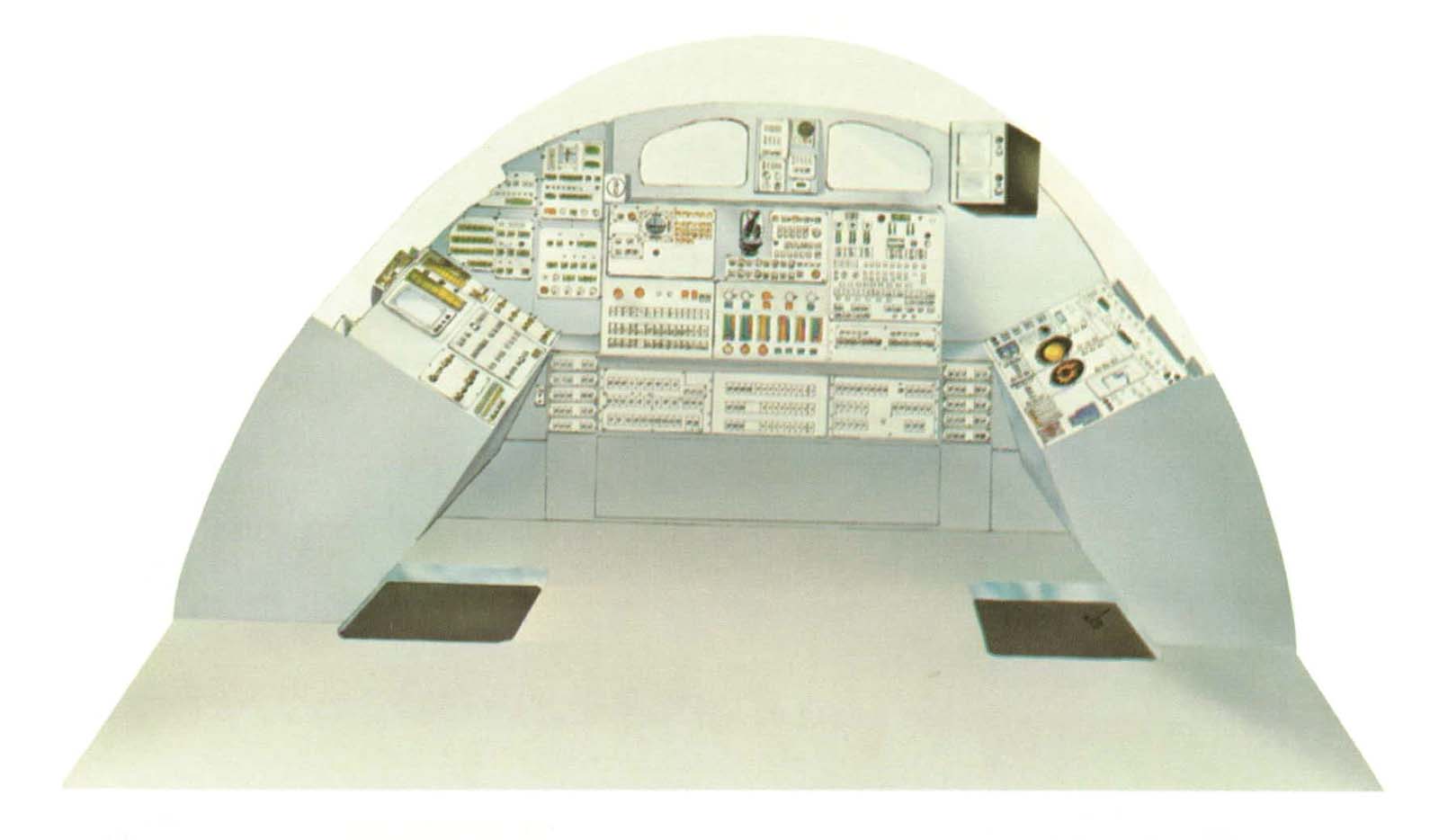
The forward-facing primary flight stations are organized in the usual pilot-copilot relationship, with duplicated controls that permit the vehicle to be piloted from either seat or returned to Earth by one crewmember in an emergency. Manual flight controls include rotation and translation hand controllers, rudder pedals, and speed brake controllers at each station.
The payload handling station, the aft-facing station nearest to the payload station, contains those displays and controls required to manipulate, deploy, release, and capture payloads. The person at this station can open and close payload bay doors; deploy the coolant system radiators; deploy, operate, and stow the manipulator arms; and operate the lights and television cameras mounted in the payload bay. Two closed circuit television monitors display video from the payload bay television cameras for monitoring payload manipulation.
The rendezvous and docking station, the aft-facing station nearest to the mission station, contains the displays and controls required to execute Orbiter attitude/translation maneuvers for terminal-phase rendezvous and docking. Located at this station are rendezvous radar controls and displays (including a crosspointer for displaying pitch and roll angles and rates), rotation and translation hand controllers, flight control mode switches, and an attitude direction indicator.
The payload station, lust aft and to the left of the commander’s station, includes a 2-square meter (21.5 square foot) surface area for installing displays and controls unique to a specific payload. A cathode ray tube (CAT) display and keyboard may be added for communication with payloads through the Orbiter data processing subsystem. Standardized electrical interfaces are provided for payload power, monitoring, command, and control. Forced-air cooling can be provided for equipment requiring heat removal.
The mission station, just aft and to the right of the pilot’s station, contains the displays and controls required to manage Orbiter/payload interfaces and payload subsystems that are critical to the safety of the Orbiter. An auxiliary caution and warning display can be provided at this station to detect and alert the crew to critical malfunctions in the payload systems. This station is equipped to monitor, command, control, and communicate with attached or detached payloads. It also provides for the management of on-orbit housekeeping functions and of Orbiter subsystem functions that are not flight critical and that do not require immediate access.
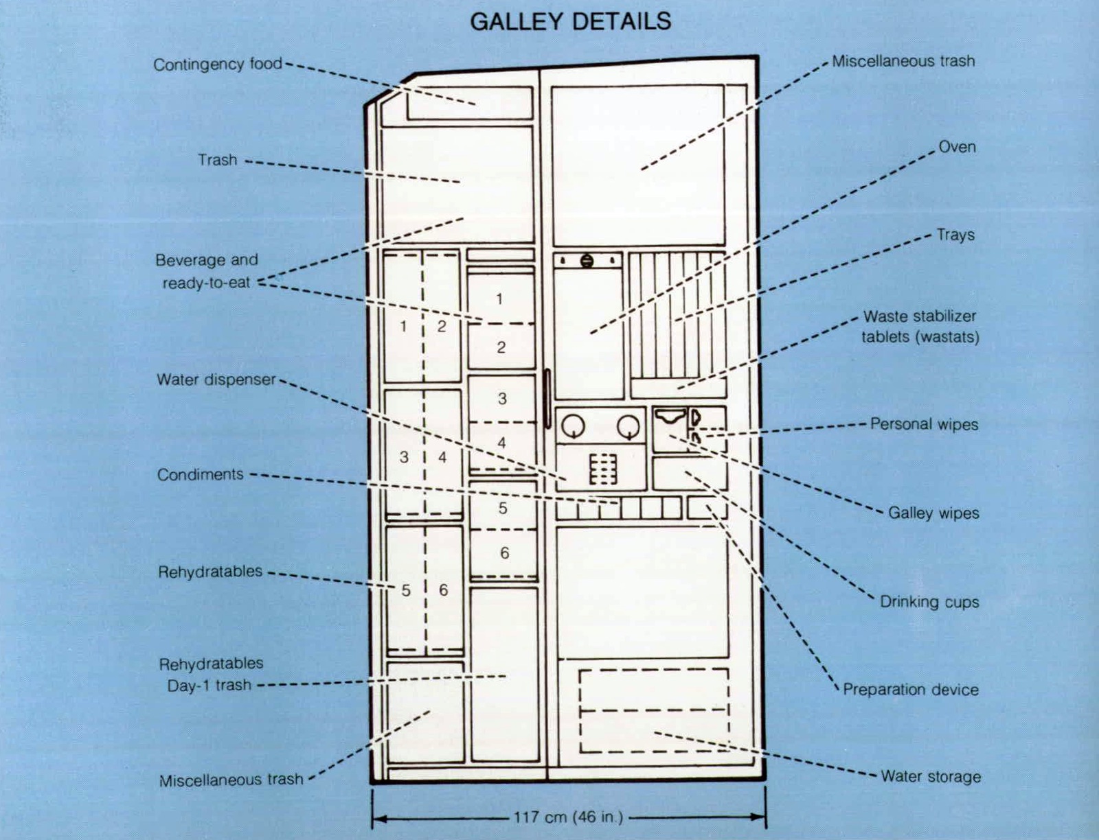
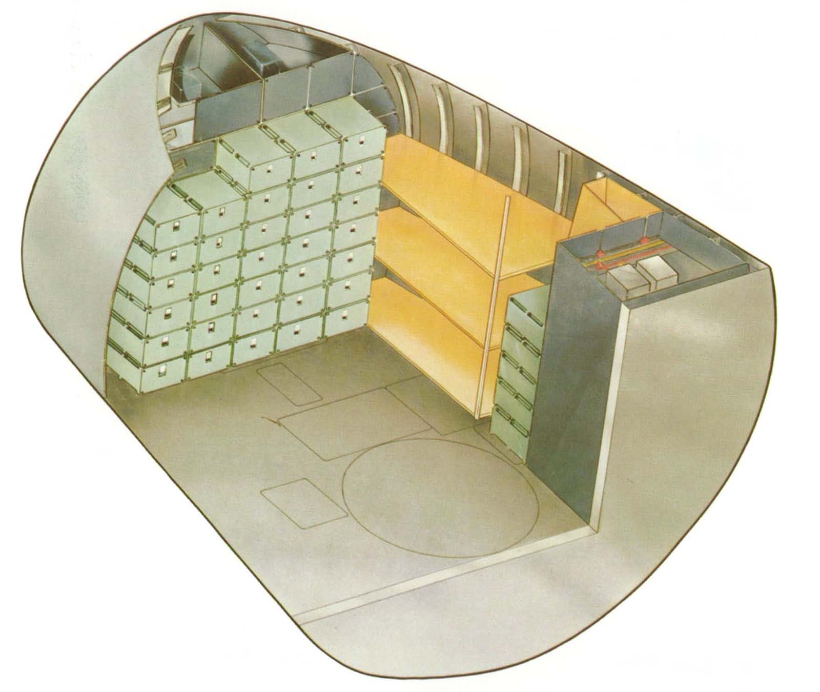
A total volume of approximately 4.2 cubic meters (150 cubic feet) will be provided in the crew compartment for Orbiter and payload loose equipment stowage, of which approximately 95 percent will be on the mid deck. Loose equipment includes those items which are not permanently mounted in the cabin. The allocation of containers to payload unique loose equipment is mission dependent. Any excess stowage capacity available above the Orbiter requirements may be utilized for stowage of payload loose equipment.
The standard containers provided for the loose equipment will be attached to the Orbiter structure in the mid-deck stowage areas. The Orbiter supporting structure to which the containers are attached has an average rated capacity of 320 kilograms per cubic meter (20 pounds per cubic foot) with a rating of 480 kilograms per cubic meter (30 pounds per cubic foot) for each attach point.
The size of packages and equipment which can be moved through the side hatch into the central mid-deck area is limited by placement of mid-deck structures as well as the opening size of the side hatch.
EXTRAVEHICULAR ACTIVITIES
A versatile extravehicular capability is provided by an airlock, two extravehicular mobility units (spacesuits), and mobility aids, such as handrails. A variety of tasks can be performed during extravehicular activity (EVA) to support either the Orbiter or its payloads. Typical tasks are as follows.
- Inspection, photography, and possible manual override of vehicle and payload systems, mechanisms, and components
- Installation, removal, and transfer of film cassettes, material samples, protective covers, and instrumentation
- Operation of equipment, including assembly tools, cameras, and cleaning devices
- Connection, disconnection, and storage of fluid and electrical umbilicals
- Repair, replacement, calibration, repositioning, and inspection of modular equipment, antennas, and instrumentation on the spacecraft or payload
The airlock can be located in several places: inside the Orbiter middle deck on the aft bulkhead, outside the cabin on the aft bulkhead, or on top of a tunnel adapter which connects the Spacelab pressurized module with the Orbiter cabin. When docking is planned, the docking module serves as the EVA airlock.
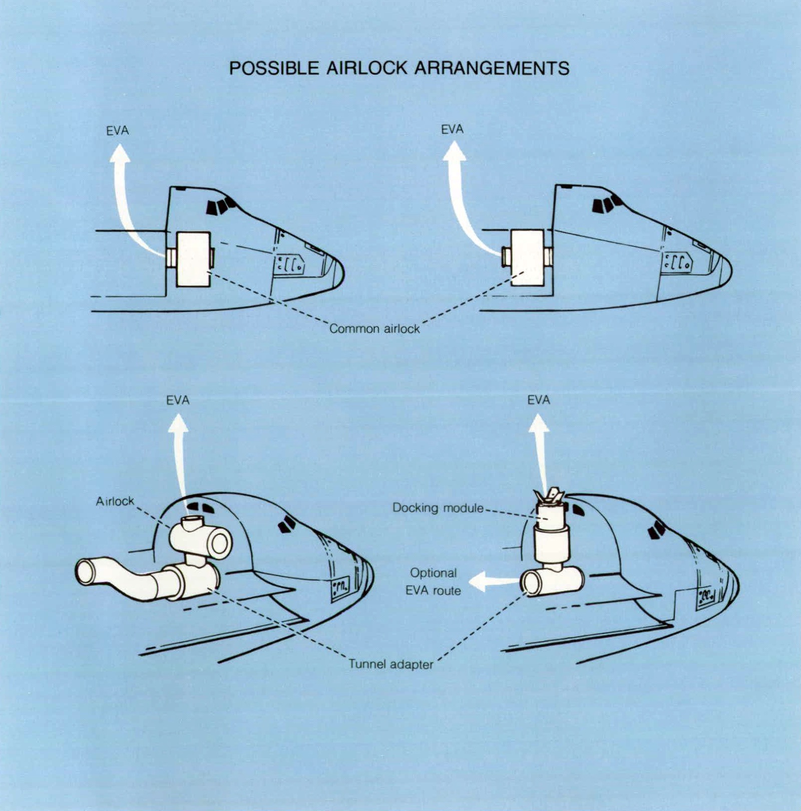
The airlock hatches are located to allow passage straight through to facilitate transfer of equipment. The hatches are D-shaped. The flat side of the D makes the minimum clearance 91 centimeters (36 inches). The inside diameter of the airlock is 160 centimeters (63 inches) and it is 211 centimeters (83 inches) long. This volume allows two EVA crewmen to transport a package 45 by 45 by 127 centimeters (18 by 18 by 50 inches) through the airlock.
Life support expendables are carried for two 6-hour payload EVA’s and one contingency or emergency EVA.
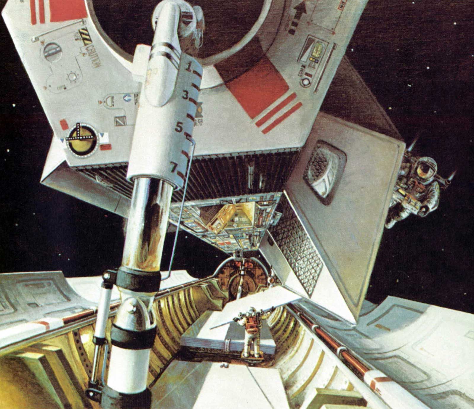
Restraints for planned EVA will normally consist of the Skylab foot restraint. Unplanned EVA in support of a payload may often be accomplished with no impact to a payload, because attachment to available structures will often provide sufficient restraint. Translation aids are provided for moving about in the payload bay. Handrails extend from the airlock hatch, down the hinge line of the door, and into the payload bay, are located at intermediate points if required, and at the aft bulkhead.
PAYLOAD ATTACHMENTS
Numerous attachment points along the sides and bottom of the 18-meter (60 foot) payload bay provide places for the many payloads to be accommodated. All primary attachment points along the sides accept longitudinal and vertical loads. All positions along the keel take lateral loads. The proposed design of the standard attachment fitting includes adjustment capability to adapt to specific payload weight distributions in the bay.
POWER SYSTEMS
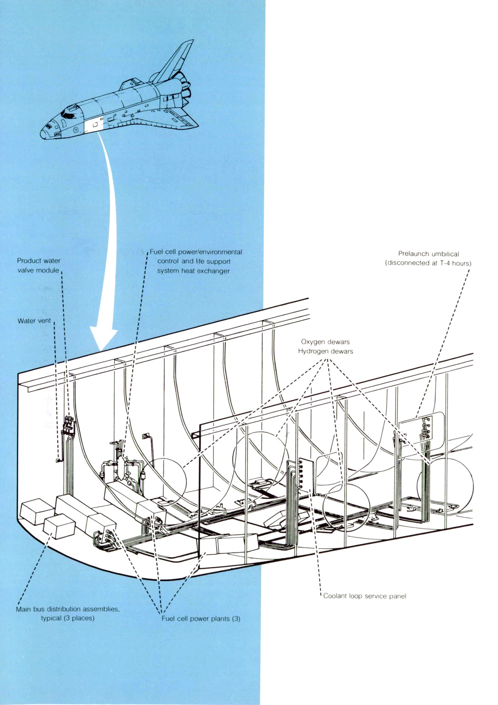
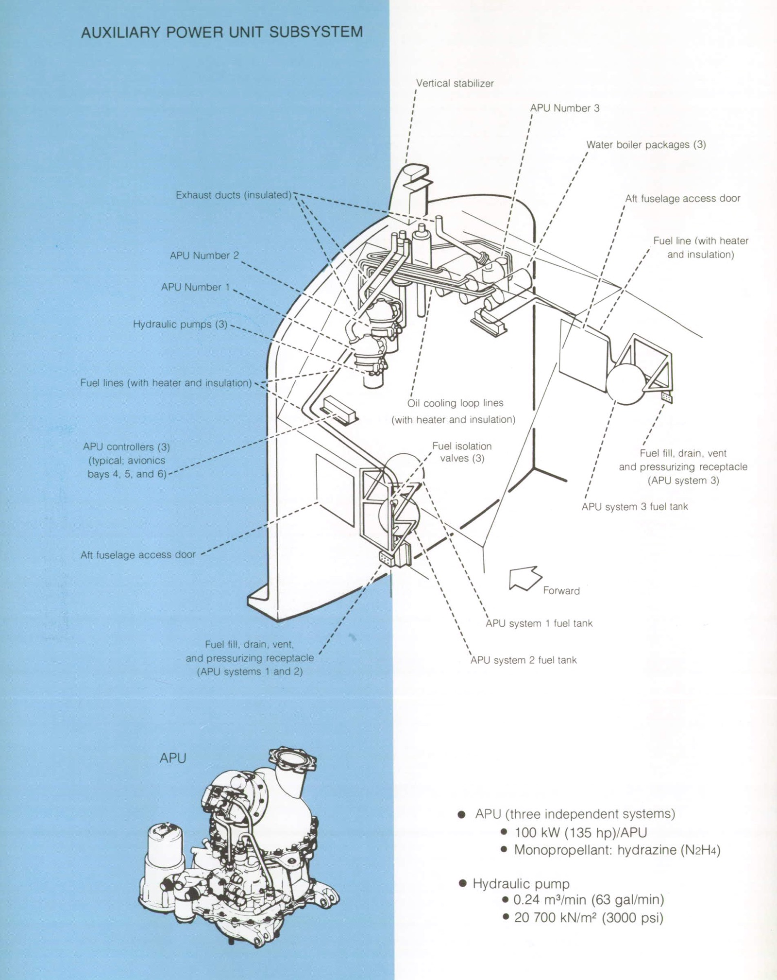
The Orbiter has one system to supply electrical power and another system to supply hydraulic power. Electrical power is generated by three fuel cells that use cryogenically stored hydrogen and oxygen reactants. Each fuel cell is connected to one of three independent electrical buses During peak and average power loads, all three fuel cells and buses are used; during minimum power loads, only two fuel cells are used but they are interconnected to the three buses. The third fuel cell is placed on standby, but can be reconnected instantly to support higher loads. Alternately, the third fuel cell is shut down under the condition of a 278 K (40° F) minimum temperature environment and can be reconnected within 15 minutes to support higher loads. Excess heat from the fuel cells is transferred to the Freon cooling loop through heat exchangers. Hydraulic power is derived from three independent hydraulic pumps, each driven by its own hydrazinefueled auxiliary power unit (APU) and cooled by its own water boiler. The three independent hydraulic fluid systems provide the power to actuate the elevons, rudder/speed brakes, body flap, main engine gimbal and control systems, landing gear brakes, and steering. While on orbit, the hydraulic fluid is kept warm by heat from the Freon loop.
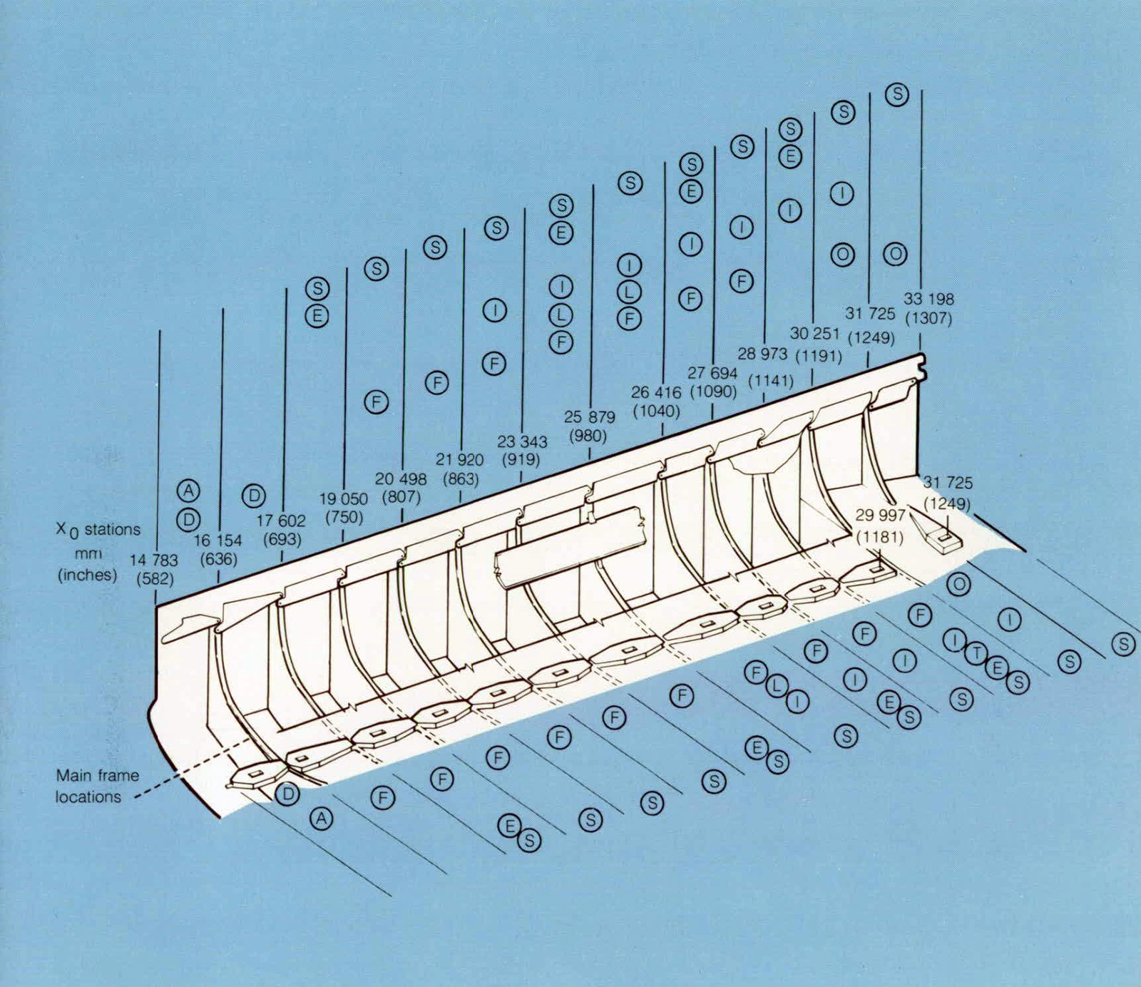
The electrical power requirements of a payload will vary throughout a mission. During the 10-minute launch-to-orbit phase and the 30-minute deorbit-to-landing phase when most of the experiment hardware is in a standby mode or completely turned off, 1000 watts average to 1500 watts peak are available from the Orbiter. During payload equipment operation on orbit, the capability exists to provide as much as 7000 watts maximum average to 12,000 watts peak for major energy-consuming payloads. For the 7-day-mission payload, 50 kilowatt-hours of electrical energy are available. Mission kits containing consumables for 840 kilowatt-hours each are available in quantities required according to the flight plan.
The operational use of fuel cells for manned space flight evolved during the Gemini and Apollo Programs, The Space Shuttle fuel cells will be serviced between flights and reflown until each one has accumulated 5000 hours of online service.
ORBITER PROPULSION AND POWER SUBSYSTEM
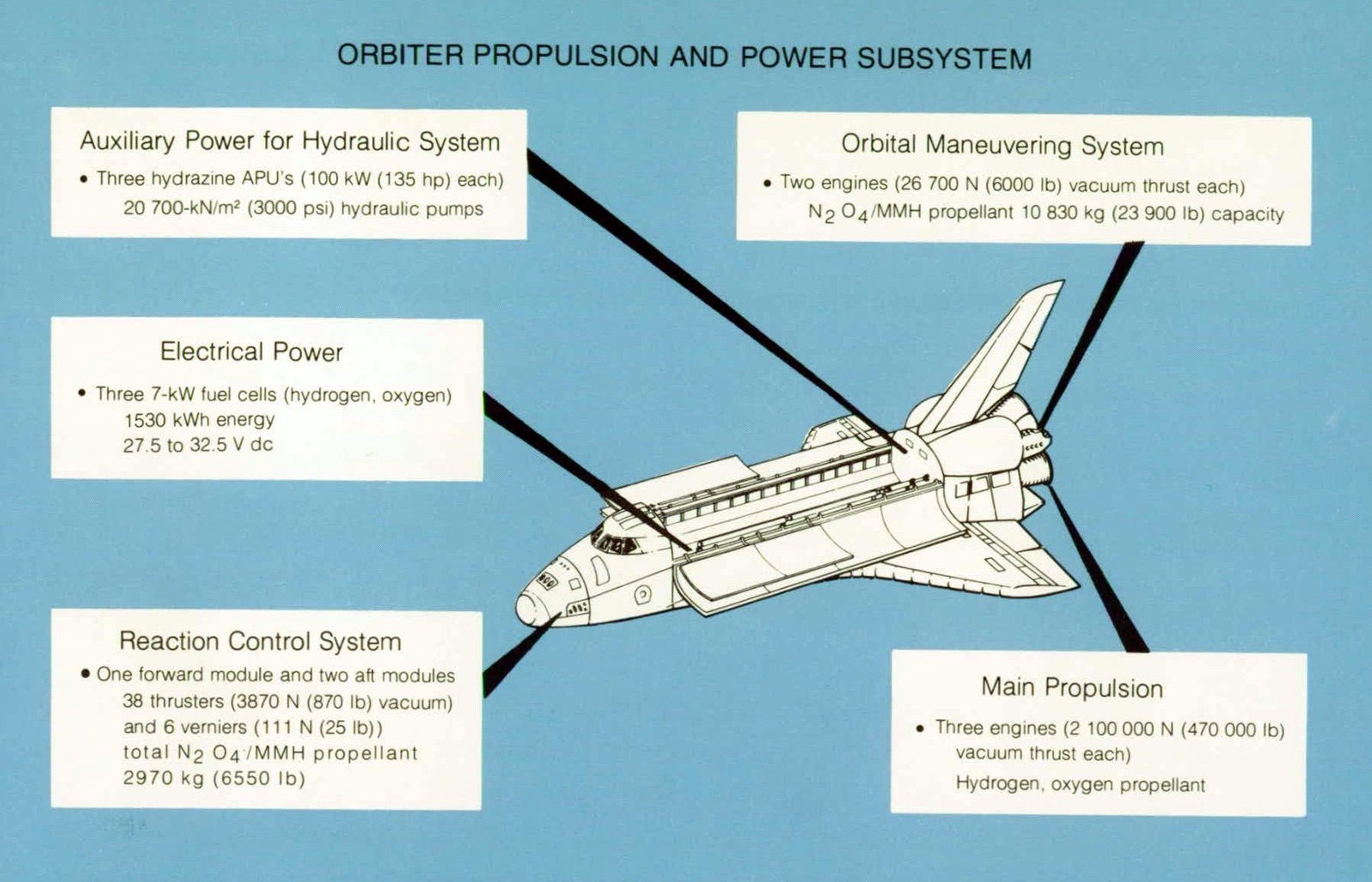
Auxiliary Power for Hydraulic System
- Three hydrazine APU’s (100 kW (135 hp) each) 20,700-kN/m2 (3000 psi) hydraulic pumps
Orbital Maneuvering System
- Two engines (26,700 N (6000 lb) vacuum thrust each) N2O4/MMH propellant 10,830 kg (23,900 lb) capacity
Main Propulsion
- Three engines (2,100,000 N (470,000 lb) vacuum thrust each)
- Hydrogen, oxygen propellant
Reaction Control System
- One forward module and two aft modules
- 38 thrusters (3870 N (870 lb) vacuum) and 6 verniers (111 N (25 lb)) total N2O4/MMH propellant 2970 kg (6550 lb)
Electrical Power
- Three 7-kW fuel cells (hydrogen, oxygen) 1530 kWh energy 27.5 to 32.5 V dc
| Mission phase | Interface | Xo station | Voltage range | Power kW | Comments | ATCSa payload heat rejection configuration, kJ/hr (Btu/hr) | |
|---|---|---|---|---|---|---|---|
| Average | Peak | ||||||
| Ground operation (ground power) | Dedicated fuel cell connector | ≈ 695 | 24 to 32 | 1 | 1.5 | Normal checkout | Limited to 5486 kJ/hr (5200 Btu/hr) with or without radiator kit unless payload has GSE connection for cooling or Orbiter is powered down |
| 27 to 32 | 7 | 12 | Orbiter powered down | ||||
| Main bus connector | ≈ 695 | 24 to 32 | 1 | 1.5 | Normal checkout | ||
| 5 | 8 | Orbiter powered down | |||||
| Aft (bus B) | 1307 | 24 to 32 | 1.5 | 2 | May be used simultaneously | ||
| Aft (bus C) | 1307 | 24 to 32 | 1.5 | 2 | |||
| Ascent/descent | Dedicated fuel cell connector | ≈ 695 | 27 to 32 | 1 | 1.5 | Power limited to a total of 1 kW average and 1.5 kW peak for 2 min | 5486 (5200) with or without radiator kit |
| Main bus connector | ≈ 695 | 27 to 32 | 1 | 1.5 | |||
| Aft (bus B) | 1307 | 24 to 32 | 1 | 1.5 | |||
| Aft (bus C) | 1307 | 24 to 32 | 1 | 1.5 | |||
| On-orbit payload operations | Dedicated fuel cell connector | ≈ 695 | 27 min Max. TBDb |
7 6 |
12 TBDb |
Peak power limited to 15 min once every 3 hr | 31,100 (29,500) (kit) 22,700 (21,500) (no kit) |
| Main bus connector | ≈ 695 | 27 to 32 | 5 | 8 | |||
| Aft (bus B) | 1307 | 24 to 32 | 1.5 | 2 | Power may be utilized from both interfaces simultaneously; buses must be isolated on the payload side of the interface | 22,700 or 31,100 (21,500 or 29,500) | |
| Aft (bus C) | 1307 | 24 to 32 | 1.5 | 2 | |||
a Active thermal control subsystem
b To be determined
ENVIRONMENTAL CONTROL
Cooling services are provided to payloads by the Space Shuttle. Ground support equipment provides a selectable temperature range during prelaunch activities. After the Orbiter lands, ground support equipment similar to airline support hardware is connected to the cabin and payload bay to control temperature levels.
The payload bay is purged with conditioned air at the launch pad until 80 minutes before the start of propellant loading, then dry nitrogen gas is supplied until lift-off. The payload bay is vented during the launch and entry phases and is unpressurized during the orbital phase of the mission. The pressure difference between the payload bay and outside air is minimized to allow a lightweight structure and thus an economical design for the payload bay.
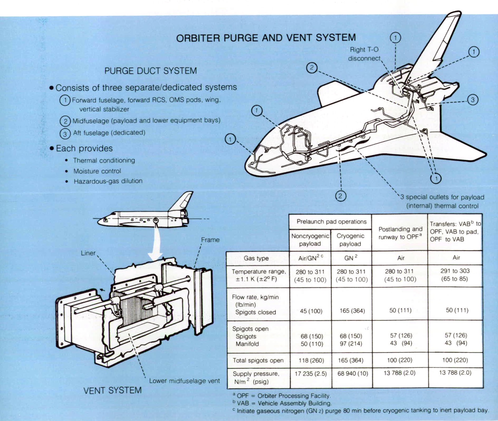
PURGE DUCT SYSTEM
- Consists of three separate/dedicated systems
- Forward fuselage, forward RCS, OMS pods, wing, vertical stabilizer
- Midfuselage (payload and lower equipment bays)
- Aft fuselage (dedicated)
- Each provides
- Thermal conditioning
- Moisture control
- Hazardous-gas dilution
| Prelaunch pad operations | Postlanding and runway to OPFa | Transfers: VABb to OPF, VAB to pad, OPF to VAB | ||
|---|---|---|---|---|
| Noncryogenic payload | Cryogenic payload | |||
| Gas type | Air/GN2 c | GN2 | Air | Air |
| Temperature range, ±1.1 K (±2° F) |
280 to 311 (45 to 100) | 280 to 311 (45 to 100) | 280 to 311 (45 to 100) | 291 to 303 (65 to 85) |
| Flow rate, kg/min (lb/min) Spigots closed |
45 (100) | 165 (364) | 50 (111) | 50 (111) |
| Spigots open Spigots Manifold |
68 (150) 50 (110) |
68 (150) 97 (214) |
57 (126) 43 (94) |
57 (126) 43 (94) |
| Total spigots open | 118 (260) | 165 (364) | 100 (220) | 100 (220) |
| Supply pressure, N/m2 (psig) | 17,235 (2.5) | 68,940 (10) | 13,788 (2.0) | 13,788 (2.0) |
- a OPF = Orbiter Processing Facility.
- b VAB = Vehicle Assembly Building.
- c Initiate gaseous nitrogen (GN2) purge 80 min before cryogenic tanking to inert payload bay.
The cabin atmosphere (temperature, pressure, humidity, carbon dioxide level, and odor) is controlled by the cabin heat exchanger and associated equipment. The temperature is maintained between 289 and 305 K (61° and 90° F). An oxygen partial pressure of 22,065 ± 1725 N/m2 (3.2 ± 0.25 psia) is maintained, and nitrogen is added to achieve a total pressure of 101,355 N/m2 (14.7 psi). The oxygen is supplied from the same cryogenic tanks that supply the fuel cells. Nitrogen for normal operation and emergency oxygen is supplied from 20,700-kN/m2 (3000 psi) pressure vessels mounted in the midfuselage. The cabin atmosphere and part of the avionic equipment cooling is controlled by air that is ducted through the cabin heat exchanger.
The radiator system located on the inside of the payload bay doors is the primary on-orbit heat rejection system. A water loop transports the excess heat from the cabin heat exchanger and remaining avionic equipment (through cold plates) to the Freon cooling loop by way of the cabin heat interchanger. The Freon cooling loop delivers this heat, together with heat from the fuel cells, payloads, and cold plates of the aft avionic equipment, to the 113-square-meter (1220 square foot) (effective area) baseline radiators, where the heat is radiated into space. The water flash evaporator is used to supplement the radiator cooling capacity. Extra radiator panels can be added to accommodate payloads with high heat loads.
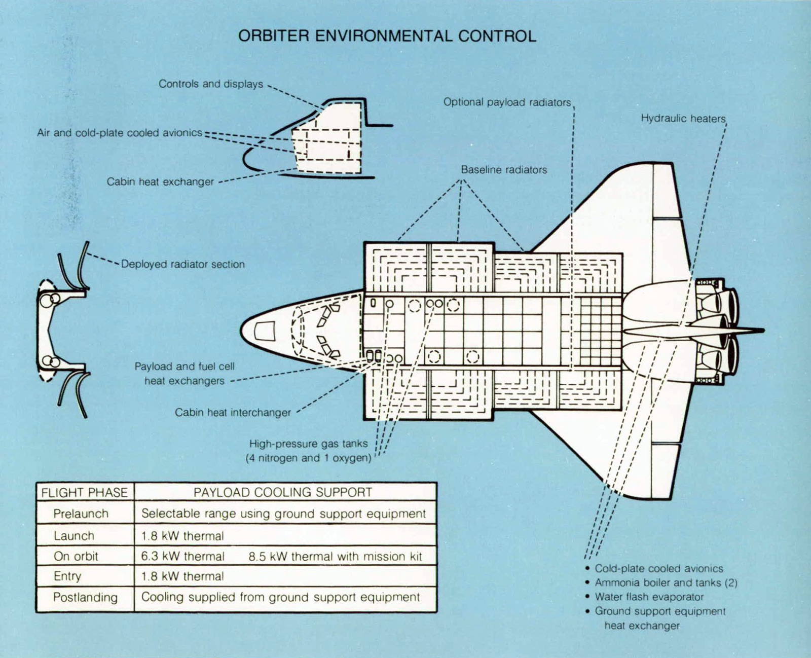
| FLIGHT PHASE | PAYLOAD COOLING SUPPORT |
|---|---|
| Prelaunch | Selectable range using ground support equipment |
| Launch | 1.8 kW thermal |
| On orbit | 6.3 kW thermal 8.5 kW thermal with mission kit |
| Entry | 1.8 kW thermal |
| Postlanding | Cooling supplied from ground support equipment |
During the ascent and descent (down to an altitude of 30,500 meters (100,000 feet), when the cargo bay doors are closed and the radiators are ineffective), cooling is provided by the flash evaporator. From the altitude of 30,500 meters (100,000 feet) to landing and connection with the ground support equipment, the ammonia boiler provides the required cooling.
AVIONICS
The Shuttle avionics subsystem provides commands; guidance and navigation (G&N) and control; communications; computations; displays and controls; instrumentation; and electrical power distribution and control for the Orbiter, the external tank, and the SRB. The avionics equipment is arranged to facilitate checkout, access, and replacement with minimal disturbance to other subsystems. Almost all electrical and electronic equipment is installed in three areas of the Orbiter: the flight deck, the forward avionic equipment bays, and the aft avionic equipment bays.
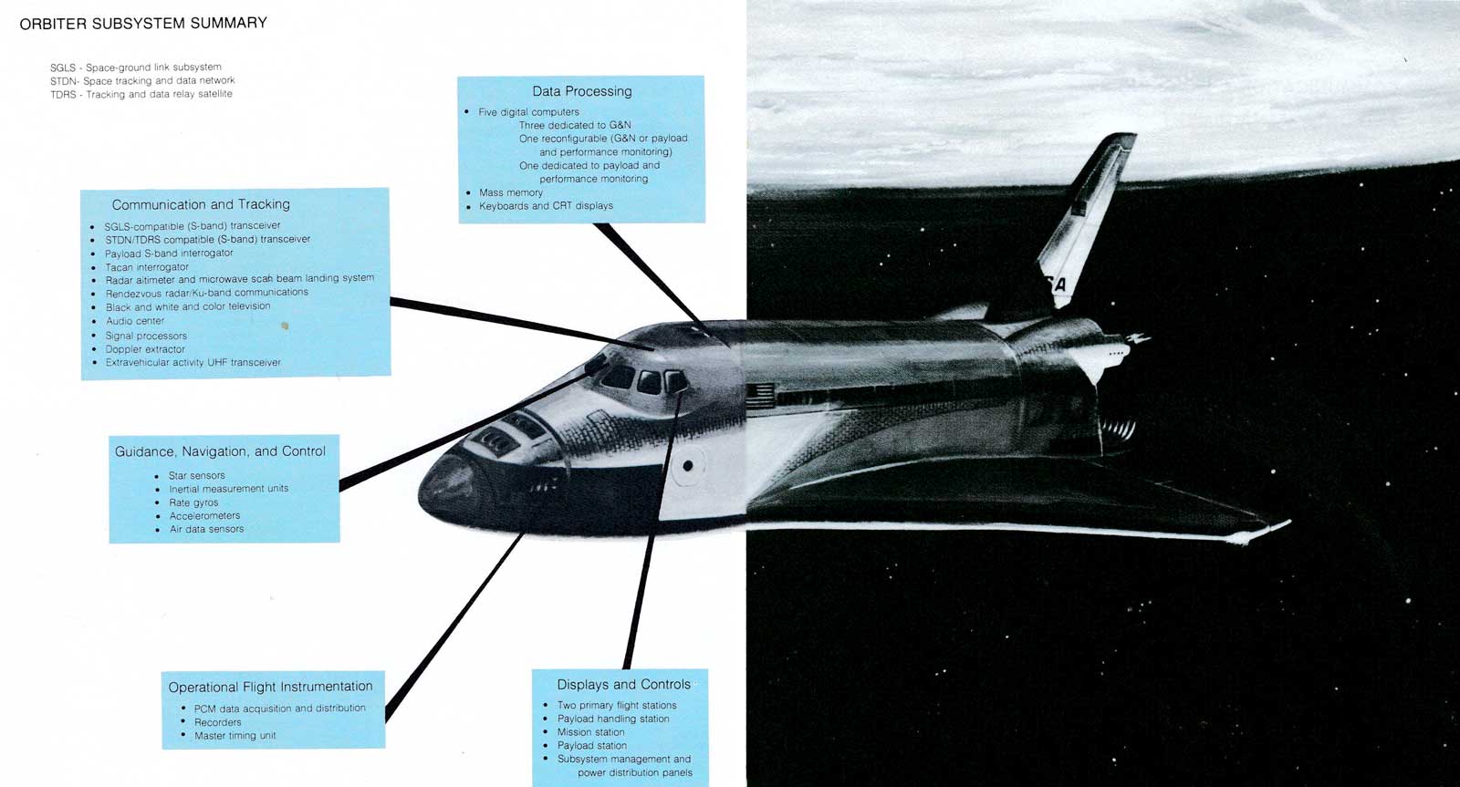
ORBITER SUBSYSTEM SUMMARY
Communication and Tracking
- SGLS-compatible (S-band) transceiver
- STDN/TDRS compatible (S-band) transceiver
- Payload S-band interrogator
- Tacan interrogator
- Radar aitimeter and microwave scan beam landing system
- Rendezvous radar/Ku-band communications
- Black and white and color television
- Audio center
- Signal processors
- Doppler extractor
- Extravehicular activitv UHF transceiver
Guidance, Navigation, and Control
- Star sensors
- Inertial measurement units
- Rate gyros
- Accelerometers
- Air data sensors
Operational Flight Instrumentation
- PCM data acquisition and distribution
- Recorders
- Master timing unit
Data Processing
- Five digital computers
- Three dedicated to G&N
- One recontigurable (G&N or payload and performance montoring)
- One dedicated to payload and performance monitoring
- Mass memory
- Keyboards and CRT displays
Displays and Controls
- Two primary flight stations
- Payload handling station
- Mission station
- Payload station
- Subsystem management and power distribution panel
- SGLS
- Space-ground link subsystem
- STDN
- Space tracking and data network
- TDRS
- Tracking and data relay satellite
The Orbiter flight deck is the center of both in-flight and ground activities except during hazardous servicing. Automatic vehicle flight control is provided for all mission phases except docking; manual control options are available at all times Side-stick rotation controllers, rudder pedals, and trim controls allow manual control, and a computer provides commands for automatic flight control to the aerosurfaces or propulsive elements as required. Attitude information is obtained from the inertial measuring unit. Air data are provided by redundant probes deployed at lower altitudes. Gimbaled inertial measuring units provide the navigation reference with star sensors for autonomous alinement and state vector update. During active rendezvous, a rendezvous radar is used to obtain range and bearing information. Orbiter-to-ground communication is by radiofrequency transmission in both frequency modulation and pulse code modulation (PCM) modes.
COMMUNICATIONS, TRACKING, AND DATA MANAGEMENT
The payload communications, tracking, and data management baseline configuration has sufficient flexibility to accommodate most payloads so that between-flight changes will be required only infrequently for special missions. Voice, television, and data-handling capabilities support onboard control or remote control from the ground when desirable. The on-orbit and ground facility handling system must be very efficient to support the many payloads to be flown.
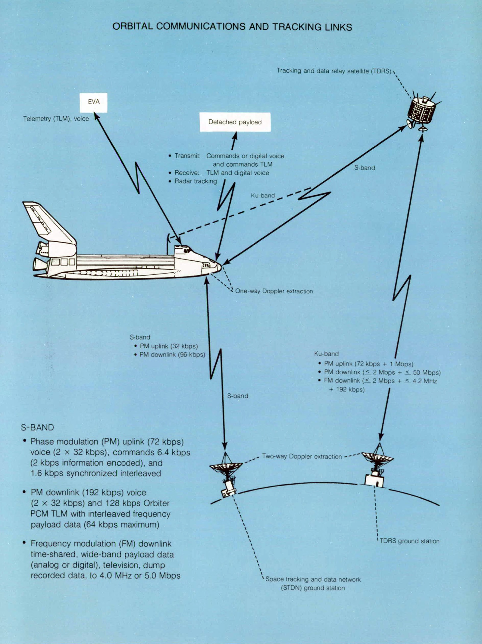
S-BAND
- Phase modulation (PM) uplink (72 kbps) voice (2 × 32 kbps), commands 6.4 kbps (2 kbps information encoded), and 1.6 kbps svnchronized interleaved
- PM downlink (192 kbps) voice (2 × 32 kbps) and 128 kbps Orbiter PCM TLM with interleaved frequency pavload data (64 kbps maximum)
- Frequency modulation (FM) downlink time-shared, wide-band payload data (analog or digital), television, dump recorded data, to 4.0 MHz or 5.0 Mbps
The communications and tracking subsystem in the Orbiter supports Orbiter-to-payload communications as well as the transfer of payload telemetry, uplink data commands, and voice signals to and from the space networks.
The data processing and software subsystem furnishes the onboard digital computation required to support payload management and handling. Functions in the computer are controlled by the crew through main memory loads from the tape memory. Flight deck stations for payload management and handling are equipped with data displays, CRT’s, and keyboards for monitoring by the crew and for controlling payload operations on a flight-by-flight basis using equipment supplied as part of the payload.
PAYLOAD POINTING AND STABILIZATION
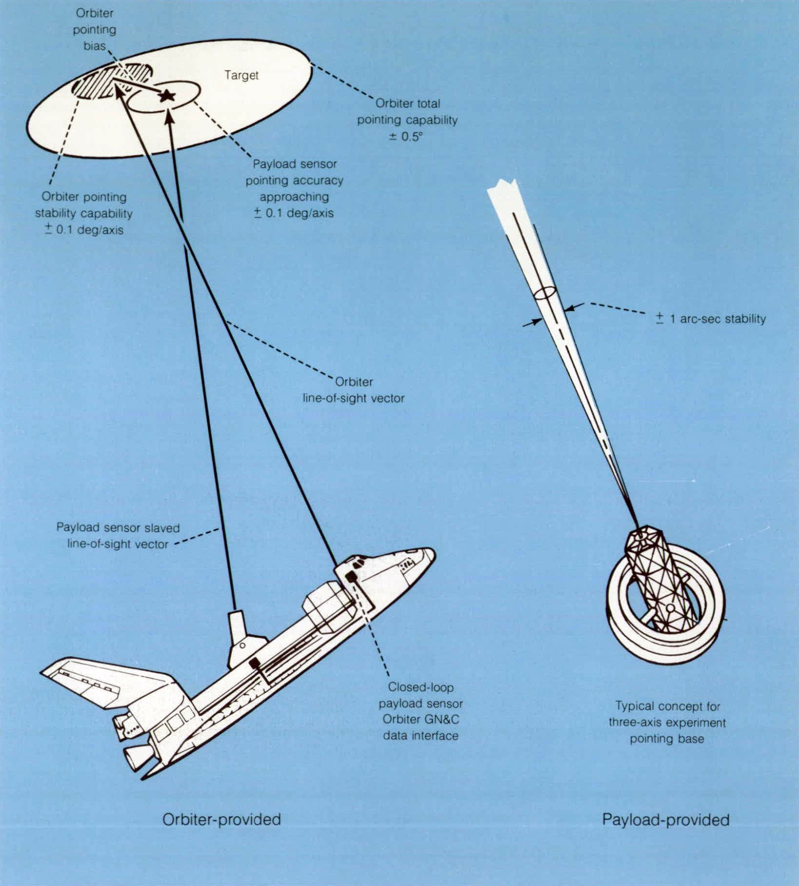
The Orbiter is Capable of achieving any desired vehicle attitude and initiating a pointing vector defined in its sensor-fixed axis system to any ground or celestial object within an accuracy of ± 0.5°. Pointing vector accuracies with respect to an open loop payload sensorfixed axis system are not as exact as the vehicle pointing accuracies because large misalinement and structural deformation error sources exist between the sensors. However, when the Orbiter guidance, navigation, and control system and a more accurate payload-mounted sensor are operated in a closed loop, payload pointing accuracies approaching ±0.1 deg/axis are possible. In either case, the Orbiter can be stabilized at a rate as low as ±0.01 deg/sec. Payloads requiring more stringent pointing and stability accuracies must provide their own stabilization and control system for that particular experiment. Orbiter guidance, navigation, and control system data interfaces are also provided to accommodate these types of payload requirements.
GUIDANCE, NAVIGATION, AND CONTROL SUBSYSTEM
The Orbiter guidance, navigation, and control (GN&C) system is capable of providing guidance, navigation, and control for the Orbiter through all phases of orbital space flight from launch through entry, and for aircraft aerodynamic flight modes. During the on-orbit phases, the guidance and navigation of the Orbiter can be independent of direct ground support. Information from the GN&C computer subsystem can be transferred to the payload bay via hardwire. As a minimum, the information will include timing, state vector initialization and extrapolation (if desired), and spacecraft attitudes and attitude rates.
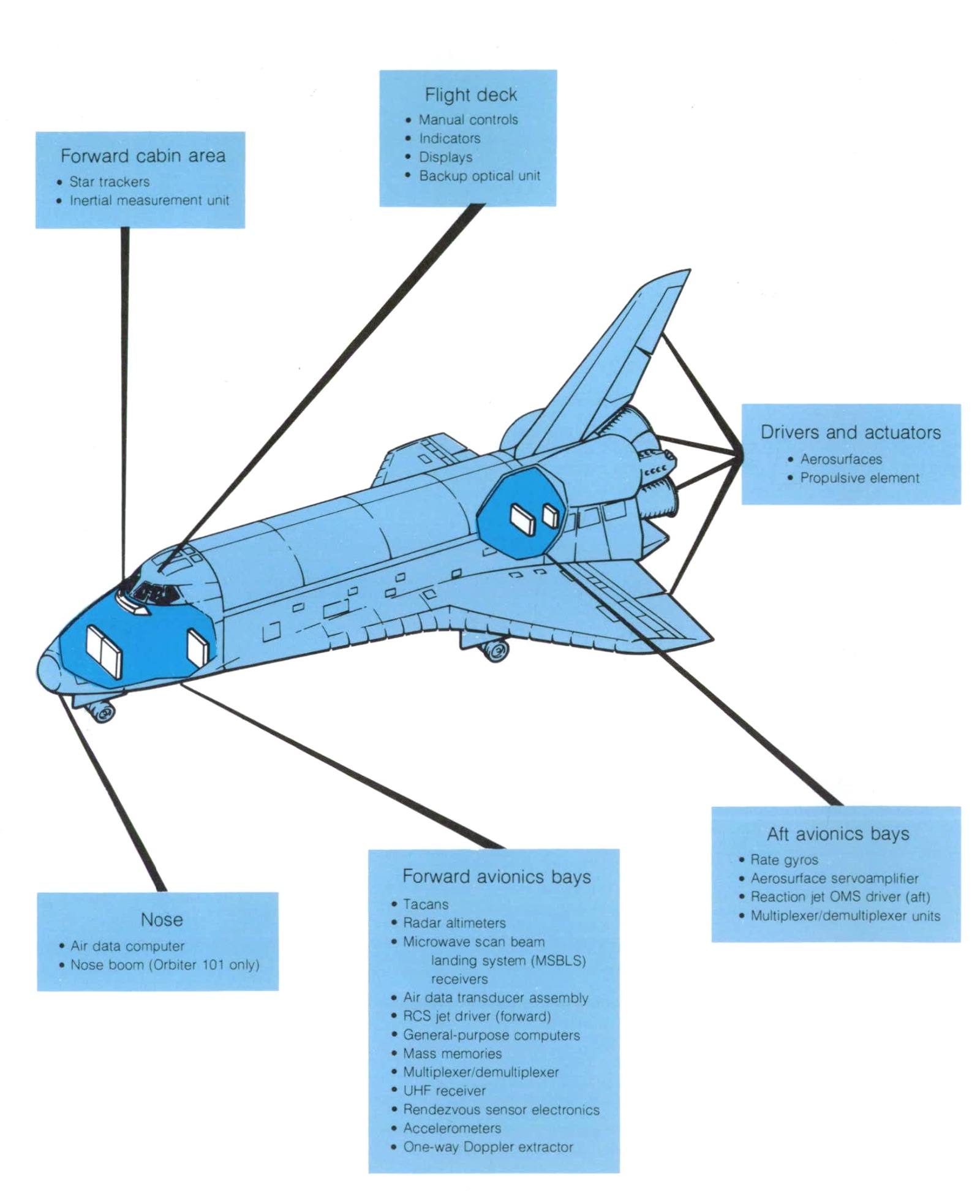
Forward cabin area
- Star trackers
- Inertial measurement unit
Flight deck
- Manual controls
- Indicators
- Displays
- Backup optical unit
Drivers and actuators
- Aerosurfaces
- Propulsive element
Aft avionics bays
- Rate gyros
- Aerosurface servoamplifier
- Reaction jet OMS driver (aft)
- Multiplexer/demultiplexer units
Forward avionics bays
- Tacans
- Radar altimeters
- Microwave scan beam landing system (MSBLS) receivers
- Air data transducer assembly
- RCS jet driver (forward)
- General-purpose computers
- Mass memories
- Multiplexer/demultiplexer
- UHF receiver
- Rendezvous sensor electronics
- Accelerometers
- One-way Doppler extractor
Nose
- Air data computer
- Nose boom (Orbiter 101 only)
The Orbiter has the onboard capability to rendezvous with an in-plane cooperative target up to 560 kilometers (300 nautical miles), and is the active vehicle during rendezvous, docking, and undocking. By using ground facilities and other aids, the Orbiter is capable of rendezvous with and retrieval of a passive stabilized orbiting element.
The dominant errors involved in pointing a payload with the spacecraft systems are contributed by the structural misalignments and thermal distortions. The guidance and navigation (G&N) subsystem errors, including an equivalent angular error due to navigation uncertainty, are less at 0.2° (1 sigma). Control system errors (i.e., attitude deadband excursions) must also be added to the stated error sources.
The Orbiter is capable of pointing the payload continuously for one orbit every other orbit for one 24-hour period per mission at any ground, celestial, or orbital object within ±0.5. Payload requirements in excess of this capability should be provided by the payload or experiment systems.
REUSABLE SPACE HARDWARE
The Space Shuttle era will emphasize operational reuse of flight hardware, which will result in low cost per flight to the users. Low cost was and continues to be the basic concept on which the total space transportation system is being developed. In addition, the Space Shuttle operational phase will last much longer than the developmental phase. Multiuse mission support equipment, like the Space Shuttle Orbiter, is being readied and will also be reflown in support of a wide variety of payloads.
MISSION KITS
A group of mission kits to provide special or extended services for payloads will be added when required and will be designed to be quickly installed and easily removed. The major mission kits are as follows.
- Oxygen and hydrogen for fuel cell usage to generate electrical energy
- Life support for extended missions
- Added propellant tanks for special on-orbit mission maneuvers
- Extra or specialized attachment fittings
- Airlocks, transfer tunnels, and docking modules
- A second remote manipulator arm and an extra high-gain antenna
- Fill, vent, drain, purge, and dump lines
- Additional radiator panels for increased heat rejection
- Additional storage tanks
- Electrical harnesses
LAUNCH SITES, OPERATIONAL DATE PREFORMACE AND INCLINATION LIMITS
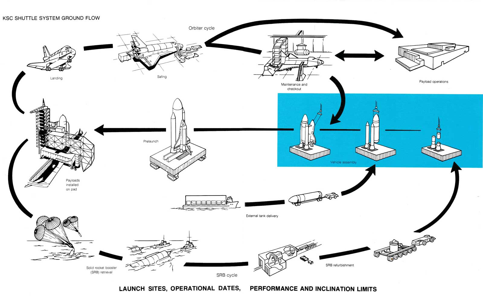
Space Shuttle flights will be launched from two locations, the NASA John F. Kennedy Space Center (KSC) in Florida and the Vandenberg Air Force Base (VAFB) in California. Present program planning calls for a gradual buildup of 40 to 60 total flights per year into many varying orbits and inclinations.
To attain operational status by 1980, Space Shuttle orbital test flights are scheduled to begin from KSC during 1979; VAFB is planned to be available in the early 1980’s.
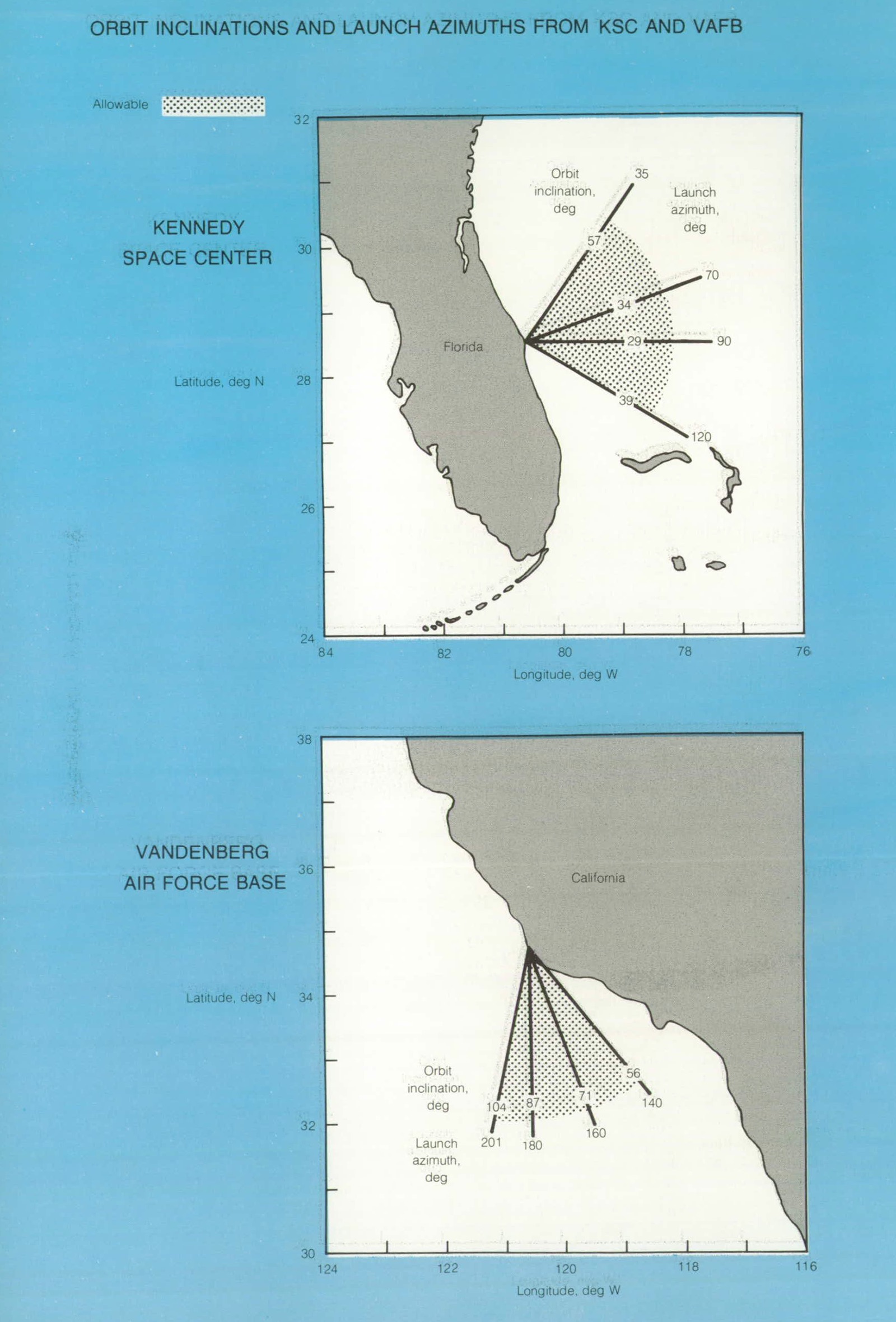
ORBIT INCLINATIONS AND LAUNCH AZIMUTHS FROM KSC AND VAFB
| Orbit inclination, deg. | Launch azimuth, deg |
|---|---|
| 57 | 35 |
| 34 | 70 |
| 29 | 90 |
| 39 | 120 |
| Orbit inclination, deg. | Launch azimuth, deg |
|---|---|
| 104 | 201 |
| 87 | 180 |
| 71 | 160 |
| 56 | 140 |
Launch Complex 39 and the Vehicle Assembly Building at KSC, used for the Apollo and Skylab Programs, will be modified for Space Shuttle use. Modification includes widening the doors approximately 12.2 meters (40 feet) to accommodate the Orbiter wingspan.
The KSC launch pads themselves will undergo major changes. Whereas launch towers for the Apollo/Saturn were on the mobile launcher platform, the towers for Shuttle will be fixed at each launch pad.
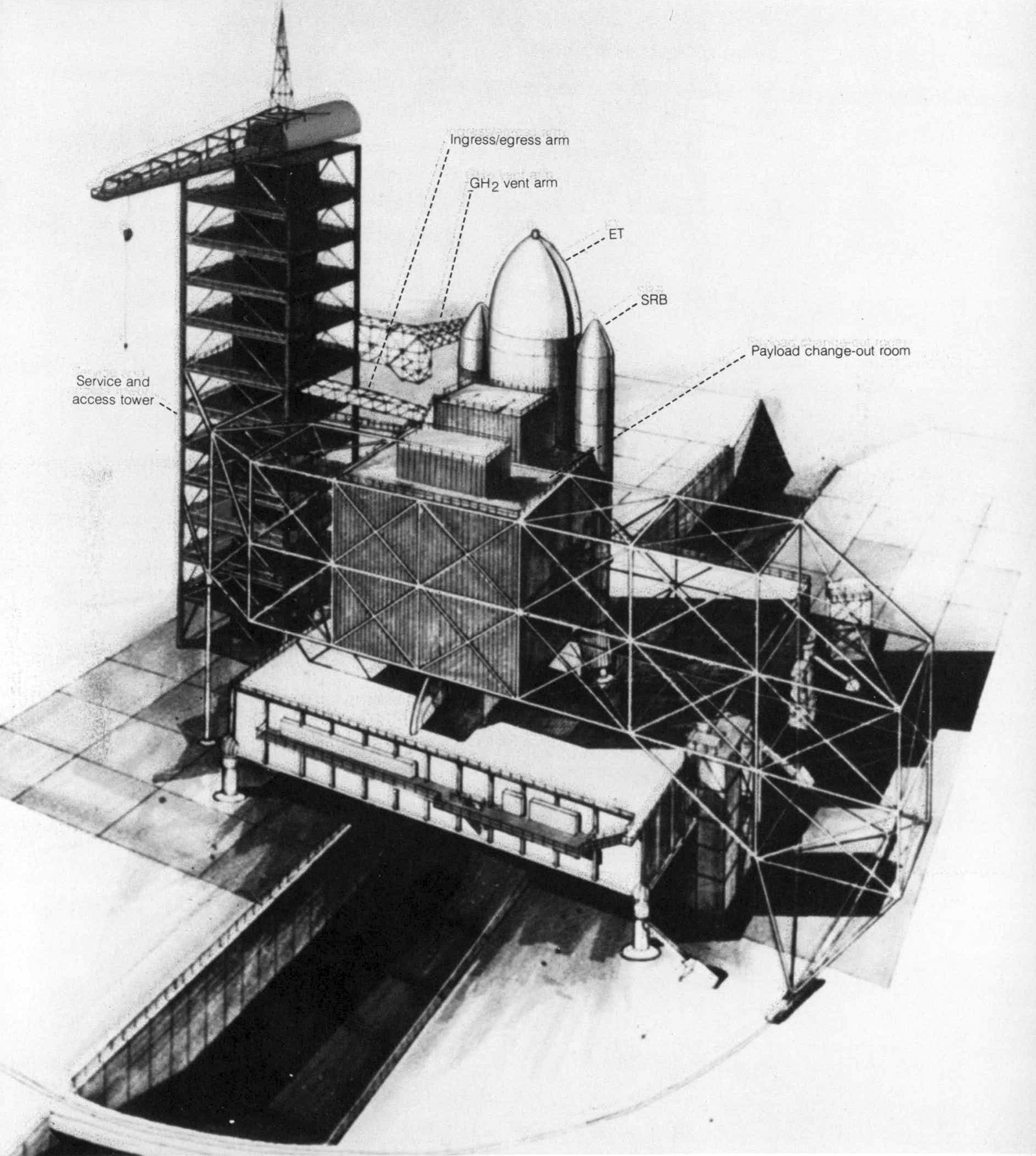
The solid rocket boosters will be received, processed, stored, disassembled, and refurbished nearby. Most of this work space will be in existing buildings. The external tank will arrive by barge at the turning basin. Payloads will be processed in various locations.
The various orbital inclinations and their related launch azimuths are illustrated for each site. Together, these capabilities satisfy all known future requirements. Payloads as large as 29,500 kilograms (65,000 pounds) can be launched due east from KSC into an orbit of 28.5° inclination. Payloads of 14,500 kilograms (32,000 pounds) can be launched from VAFB into an orbit as high as 104° inclination. Polar orbiting capabilities up to 18,000 kilograms (40,000 pounds) can be achieved from VAFB.
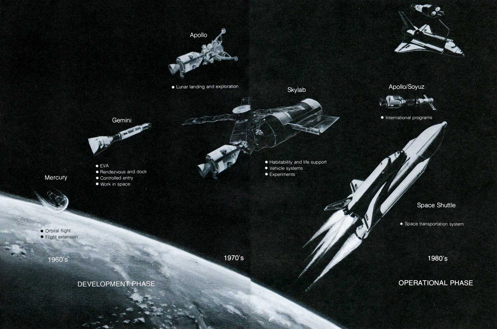
U.S. MANNED SPACE-FLIGHT OVERVIEW
DEVELOPMENT PHASE - 1960s-1970s
Mercury
- Orbital flight
- Flight extension
Gemini
- EVA
- Rendezvous and dock
- Controlled entry
- Work in space
Apollo
- Lunar landing and exploration
OPERATIONAL PHASE - 1980s
Skylab
- Habitability and life support
- Vehicle systems
- Experiments
Apollo/Soyuz
- International programs
Space Shuttle
- Space transportation system

| Program | Mercury | Gemini | Apollo | Skylab | Apollo/Soyuz |
|---|---|---|---|---|---|
| Program man-hours in space | 54 | 1940 | 7506 | 12,351 | 652 |
| Number of manned flights | 6 | 10 | 11 | 3 | 1 |
| Crew size | 1 | 2 | 3 | 3 | 3 |