6. The Amazing Orbiter
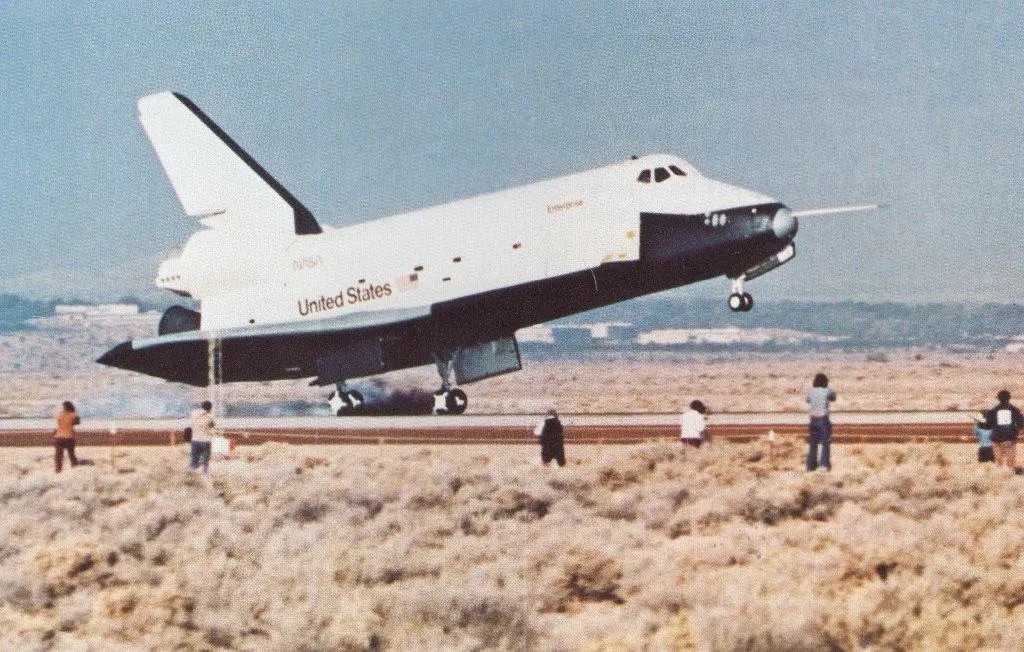
The orbiter, which all other elements of the Space Transportation System support or depend on, looks like an airplane and acts like one during the last minutes of flight. But it is far more complex than the most sophisticated aircraft: forty-nine engines, twenty-three antennas, five computers, separate sets of controls for flying in space and in the air, electric-power generators that also produce drinking water.
The thick-bodied, delta-winged aerospace craft is 37 meters long, has a span of 24 meters (120 ft by 80 ft), and weighs about 75,000 kilograms empty (165,000 lb). Its cargo bay, 18.3 meters long and 4.6 meters in diameter (60 ft by 15 ft), can deliver single or mixed payloads of up to 29,500 kilograms (65,000 lb) to orbits of up to 370 kilometers altitude, or smaller loads up to 1110 kilometers (230 mi to 690 mi). It can bring payloads of 14,515 kilograms (32,000 lbs) back to Earth; and it can carry out a variety of missions lasting seven to thirty days. It normally carries a crew of three astronauts and one to four scientists or technicians to manage the payloads.
The airframe is mostly aluminum protected by reusable surface insulation. The main sections are the forward fuselage, containing the air-tight crew module; the cargo-carrying mid-fuselage, with full-length overhead doors; the aft fuselage, including the engine thrust structure and the body flap that controls the craft’s pitch in atmospheric flight and shields the main engines from the heat of air friction during reentry; the wings, which house the main landing gear; and the vertical tail.
The forward fuselage is made of aluminum alloy panels, frames, and bulkheads, with window frames of machined parts attached to the structural panels and frames. The crew module, which will be described more fully in the next chapter, is machined aluminum alloy plate with integral stiffening stringers. It has a side hatch for normal entry and exit and an airlock from the crew living deck into the unpressurized cargo bay.
The mid-fuselage is the primary load-carrying structure between the forward and aft fuselage. The skin is machined and honeycomb-sandwich panels and the frames a combination of aluminum panels with riveted or machined integral stiffeners and a truss-structure center section. The upper half consists of the cargo hold doors, hinged along the sides and split at the top centerline. Made of graphite-epoxy composite frames and honeycomb panels, they incorporate radiators that are exposed to space when the doors are open to dissipate heat from electrical equipment in the Orbiter and payloads.
The aft fuselage structure, which carries the main-engine thrust loads to the mid-fuselage and, during ascent, to the External Tank, is a machined aluminum panel with a truss-type internal structure of titanium reinforced with boron epoxy. The wings are constructed with a corrugated spar and truss-type rib internal arrangement and skin-stringer stiffened aluminum alloy. The vertical tail is a two-spar, multi-rib, stiffened-skin box of aluminum alloy bolted to the aft fuselage at the two main spars. The rudder and speed brake assembly, divided into upper and lower sections, is aluminum honeycomb panels.
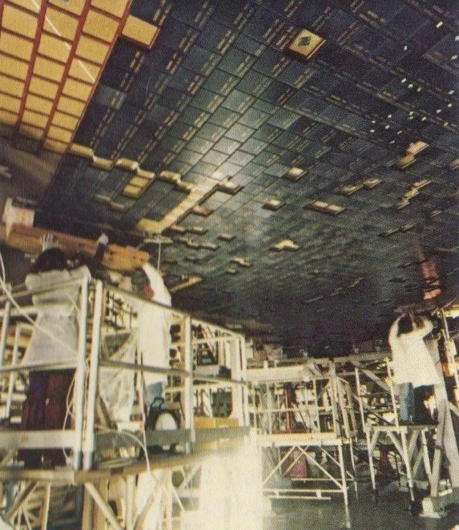
Insulation tough enough to protect the Orbiter and its crew from the searing heat of repeated reentries had to be invented. In earlier manned spacecraft, thermal buildup was controlled by shedding glowing bits of the heat shield itself. But NASA asked for materials that would last through 100 missions before replacement, and effective enough to protect the aluminum substructure beneath for 500 missions. The answer was a special tile-like insulation that reflects away heat so effectively that when one side is cool enough to hold in your bare hands, the other side can be red hot.
Two types of insulation cover the top and sides of the Orbiter: blocks of silica fiber with a glassy coating and flexible sheets of nylon felt coated with silicone. The tiles, around 2.5 centimeters thick and 20 centimeters square (1 in. by 7⅞ in. square), protect the aluminum surfaces up to 650° C, the flexible insulation up to 370° C. The coating gives the upper part of the craft a nearly white color and has optical properties that reflect solar radiation. Similar tiles with a different coating protect the bottom of the spacecraft and the leading edge of the tail up to 1260° C. The higher temperature coating gives the underside a glossy black appearance. Top and bottom, there are more than 32,000 of the tiles, for which the Orbiter has been called “the flying brickyard.” The nose and leading edge of the wings, which get hottest of all, are covered with a material called reinforced carbon-carbon (carbon cloth impregnated with additional carbon, then heat treated and coated with silicon carbide) that protects them up to 1650° C.
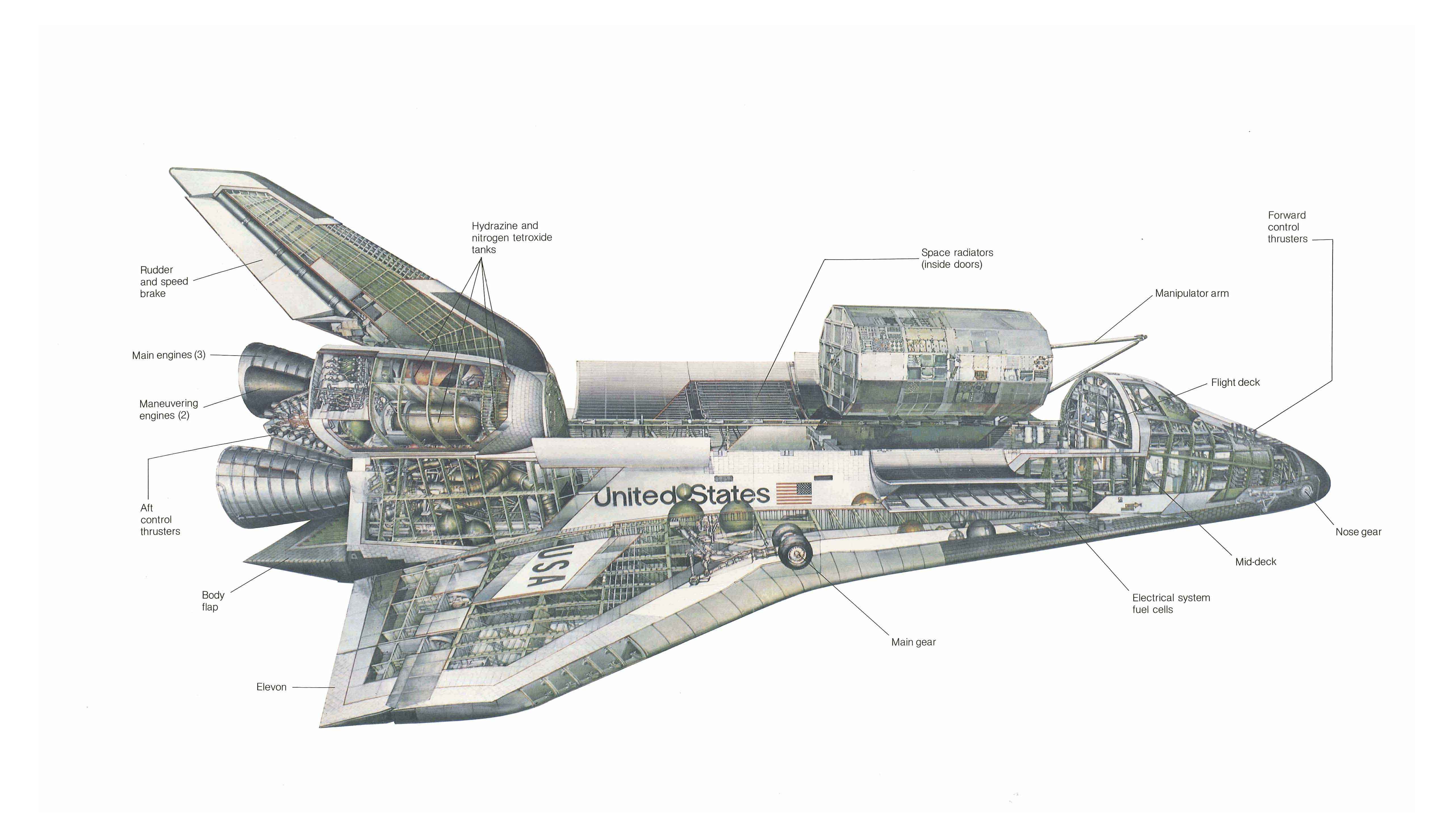
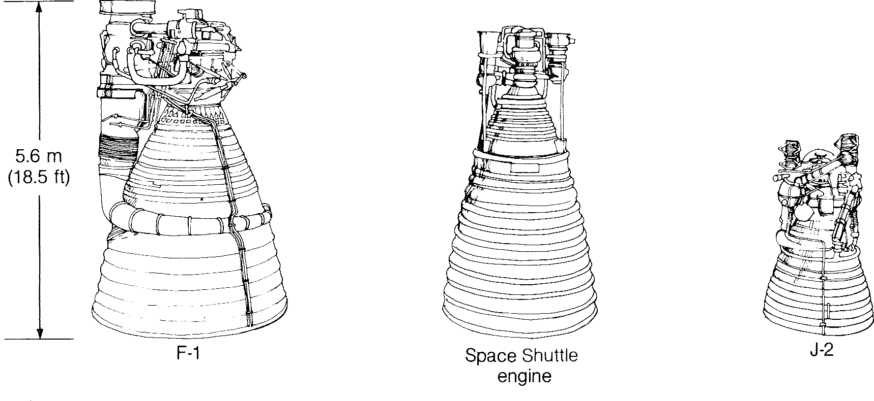
The Orbiter’s three main engines, developed by the Marshall Space Flight Center, which created the great Saturn V Moon rockets, are the most advanced rocket engines ever built and the first designed for repeated reuse. ’Their thrust for weight is the highest of any engine yet developed, and they can operate for up to seven and a half hours of accumulated firing time—fifty-five flights—before a major overhaul. Four and a third meters tall and 2.4 meters in diameter at the flare of the nozzle (14 ft by 8 ft), each produces 375,000 pounds of thrust—equivalent to about six and a half million horsepower-at the rated power level used for most launches and 470,000 pounds thrust in the vacuum of space. The thrust can be varied from 65 to 109 percent of rated power to tailor the performance to different loads and to keep acceleration within comfortable bounds.
Mounted on the Orbiter aft fuselage in a triangular pattern, the three engines can swivel 10.5 degrees up and down and 8.5 degrees from side to side during flight to change the direction of their thrust and, with the two Solid Rocket Boosters that assist during the first two minutes, steer the Shuttle as well as push. They continue to burn for six minutes after the boosters are dropped off, each minute drawing about 47,000 gallons of liquid hydrogen and 17000 gallons of liquid oxygen from the External Tank.
The propellants, ignited by devices similar to spark plugs, are burned in two stages, being partly combusted at relatively low temperature in preburners and then completely burned at high temperature in the main combustion chamber of each engine. Propellants are fed under high pressure by turbine pumps driven by hot gasses from the preburners. Operating pressure in the main combustion chamber is 3000 pounds per square inch- four times that of previous rocket engines as the fuel burns at 3515° C.
Each engine is controlled through a pair of computers (primary and backup) that monitor its operation. They compare actual with programmed performance fifty times a second; automatically correct any problems or safely shut down the engine; receive commands from the Orbiter’s guidance and navigation computers for engine start, throttle changes, and shutdown; and keep a record of the engine’s operating history for maintenance purposes.
Two orbital maneuvering engines in external pods to the left and right of the upper main engine each produce 6000 pounds of thrust to speed the Orbiter up to orbital velocity after the main engines shut down and the External Tank drops away. They also supply energy to change orbits, rendezvous with other spacecraft, and return to Earth. They burn monomethyl hydrazine as the fuel and nitrogen tetroxide as the oxidizer, which ignite on contact when mixed, requiring no starting spark. Propellants are force-fed to the engines from separate pairs of tanks in each pod by pressure from a tank of gaseous helium. The engines can be used separately or together and can be swiveled plus or minus 8 degrees to control the Orbiter’s direction. They are designed to be reusable for 100 missions and are capable of 1000 starts and fifteen hours of continuous firing.
Batteries of small rocket engines, called reaction control thrusters, in the Orbiter’s nose and near the tail provide attitude control in space and precision velocity changes for the final phases of rendezvous and docking or orbit corrections. Along with the ship’s aerodynamic control surfaces, they also control its attitude during reentry into the atmosphere and at high altitude. In the nose are fourteen primary reaction control engines, each of 870 pounds thrust, and two vernier engines of 25 pounds thrust for fine tuning. Aft, twelve primaries and two verniers nestle in each pod beside the maneuvering engine. Their propellants are the same as for the maneuvering engines, and though the reaction control thrusters have their own tanks, they can also draw on those of the maneuvering engines. Each primary engine is designed for 100 missions, 50,000 starts, and 20,000 seconds of cumulative firing, each vernier engine for 100 missions, 500,000 starts, and 125,000 seconds of firing.
Internal power for the Orbiter is supplied by separate electrical and hydraulic systems. Hydraulic power is generated by three pumps geared to gas turbines driven at 74 160 revolutions per minute by the decomposition of hydrazine as it passes over a catalyst bed. Hydraulic actuators move the elevons (wing flaps), body flap, rudder/speed brake, main-engine valves and swiveling mechanisms, landing gear, wheel brakes, nose-wheel steering gear, and devices that disconnect the propellant lines from the External Tank to the Orbiter on separation.
Electricity for everything else, from computers to the pay-load-manipulating arm, is generated by three fuel-cell power plants. Developed in earlier manned flight programs, fuel cells generate direct current through the electrochemical reaction of hydrogen and oxygen. Electrical power needed may vary from 20 to 30 kilowatts during the ten-minute ascent to orbit and the half hour of reentry and landing, when most payload equipment is turned off or on standby, up to an average of 14 kilowatts and a peak of 36 kilowatts when the equipment is in operation in orbit. A valuable byproduct of the fuel cells is drinking water for the crew and passengers.
The Orbiter’s cavernous cargo hold, with payload attachment points along its full length, is adaptable enough to accommodate as many as five unmanned spacecraft of various sizes and shapes on a single mission, instruments that view Earth or upper space from within the hold when the I doors are open, small self-contained experiments for a variety of users, or a fully equipped manned scientific laboratory, Space-lab, described more fully in Chapter 8. The Orbiter supplies them with electrical power, fluid and gas utilities, heating and cooling, data transmission or storage and displays for the payload specialists aboard, and communications with ground stations. For instruments that make their observations from platforms in the payload bay, the Orbiter’s computers fire the small vernier attitude-control thrusters to maintain pointing accuracy within half a degree.
Using radar, the Orbiter can rendezvous from 560 kilometers away (350 mi) with a cooperative target, like the space telescope, or from about 20 kilometers (12 mi) with a passive one, like the Long Duration Exposure Facility, both described in Chapter 1. Voice communications, television signals, and scientific and engineering data are transmitted and received on five frequency bands through seventeen to twenty-three antennas, depending on the mission, to and from free-flying spacecraft being deployed, serviced, or retrieved; to astronauts working in open space in their pressure suits and maneuvering backpacks; to two tracking and data relay satellites, to be launched on early Shuttle operational flights; and directly to ground stations for use by controllers and experiment managers at the Johnson Space Center, the Goddard Space Flight Center in Maryland, and the Jet Propulsion Laboratory in California
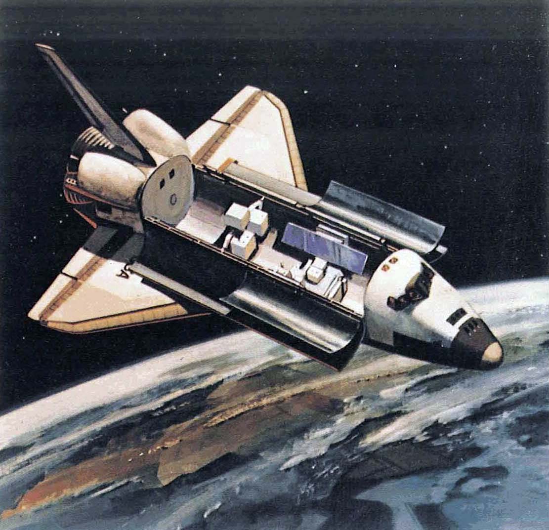
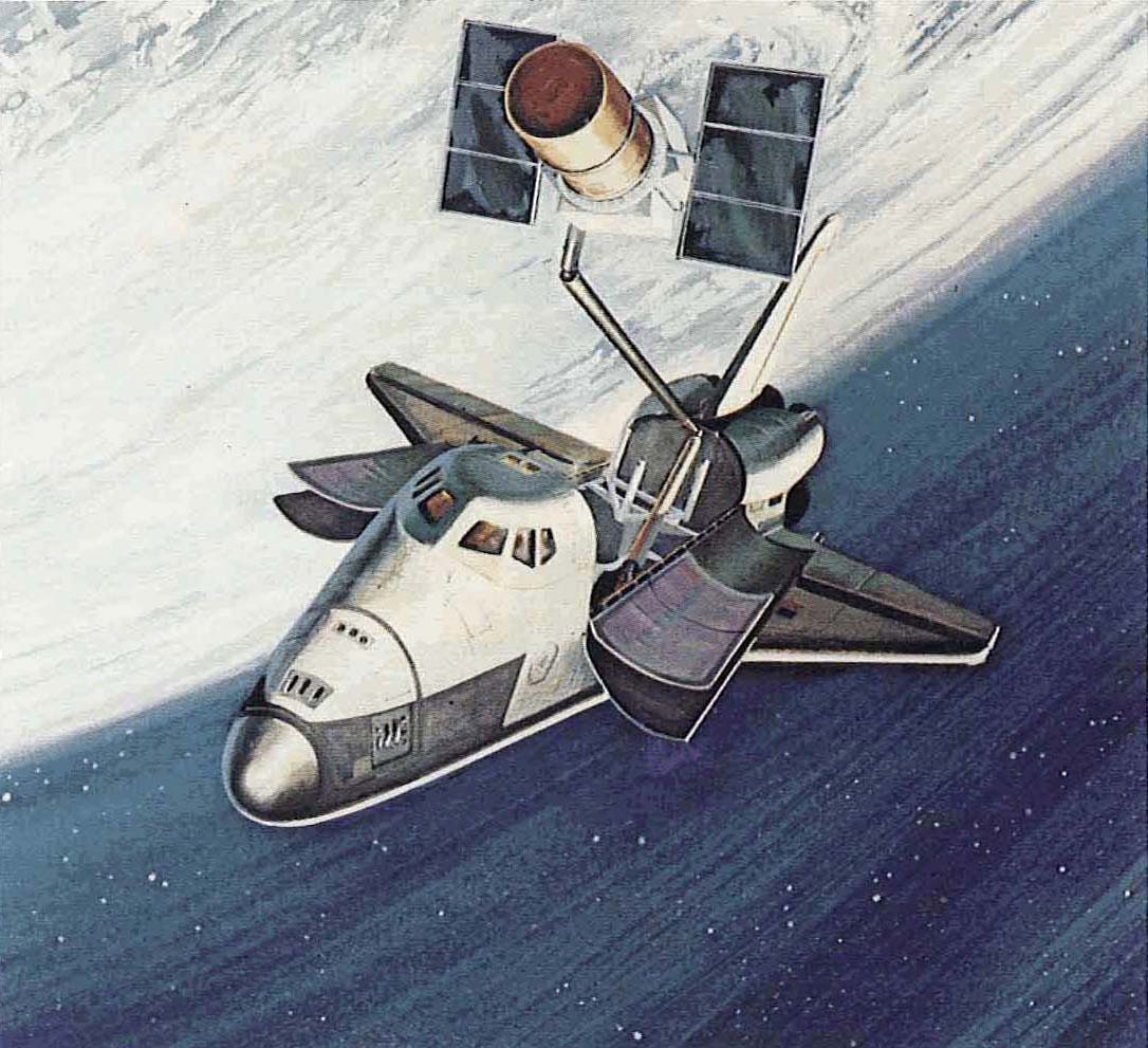
Satellites can be lifted out of or hauled into the cargo hold with a manipulating arm controlled remotely from the Orbiter flight deck. A second arm can be installed on the other side of the hold for missions on which very large or awkward payloads must be handled. Designed, developed, and built by Canadian industrial firms under the direction and funding of the National Research Council of Canada, the manipulator is a robot human arm, 15 meters long (50 ft) with joints at the shoulder, elbow, and wrist, each operated by six electric motors. It ends in a device that engineers call the “end effector” that can take hold of a spacecraft to be deployed or grab one flying outside. Television cameras on the lower arm and lights in the cargo bay help the astronaut mission specialist guide the arm’s movements from a station on the flight deck. The arm could be used to rescue the crew from a disabled Orbiter or to help assemble structures in space. There is no doubt that this ingenious electro-mechanical extension of men’s brain and muscle will perform valuable service in years to come. What is vastly less certain is that we will actually call its hand an “end effector.”
