Ground Plans for Outer-Space Ventures
The Task
By late 1962 NASA had made most of the basic decisions affecting the development of launch facilities and was ready to build the moonport. Contractors would start construction on the main buildings at launch complex 39 and in the industrial area, eight kilometers to the south, as soon as sufficient design information was available, and install equipment as construction proceeded far enough to allow safe access. At the same time, engineers were expanding and modifying the existing facilities at launch complexes 34 and 37 for earth-orbital tests of Apollo spacecraft launched by Saturn IBs.
Designers, meanwhile, were working on the final stages of the Apollo spacecraft. This complicated the design and equipment of facilities at the Launch Operations Center. The basic dimensions, weights, and operating principles of the rocket and spacecraft were known, but questions remained about specific sizes, types, quantities, flow rates, pressures, or even methods of use. Answers to many such questions awaited completion of designs at Huntsville and Houston. Policy makers had to make commitments on the basis of the best information available, knowing that costly and time-consuming changes might well become necessary.
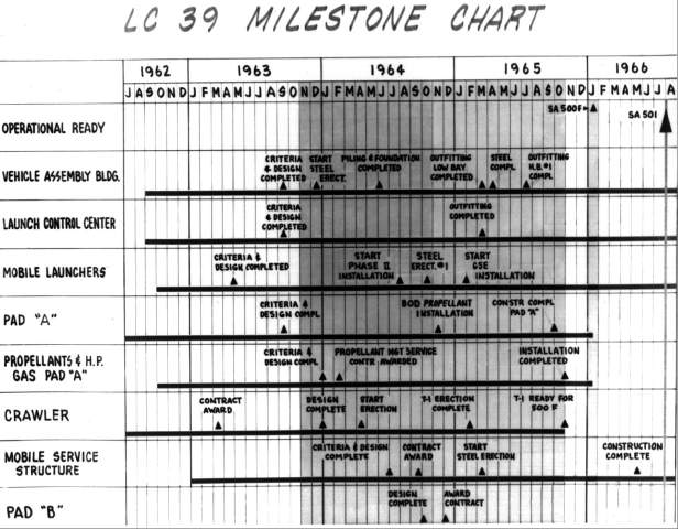
Any large construction project passes through several common stages: selecting and preparing the site, choosing or developing the equipment for use in the operation, planning the external structure, and constructing and equipping the facilities. The pressure of time was such that, during the erection of the Apollo launch facilities, what would ordinarily be consecutive steps were often simultaneous.1
By working backwards from the earliest launch date (March 1966) and estimating the time required for vehicle assembly and checkout, the date when the basic launch facilities had to be in operation could be found. Working backwards further and estimating the time required for construction and outfitting yielded the date for the start of construction. Such computations showed, in 1962, that little time remained for development of criteria and detailed design.
The requirements of the manned lunar landing program found the Launch Operations Center facing some new problems, while some old problems were becoming more acute. The new were the size and complexity of the Saturn V vehicle; the need for unprecedented reliability, flexible launch rates, and a short recovery time between launches from the same pad; and the use of the mobile concept. These, in turn, raised old questions about the marshy composition of Merritt Island and the possibility of hurricanes.
Central to LC-39 would be an assembly building, where the Saturn V vehicle would be put together. The Saturn’s size was such that the vehicle could not be transported as a unit from its place of construction, but had to be assembled and checked in a vertical attitude near the launch site. The major components were three stages, an instrument unit, and the Apollo spacecraft.
The design of the assembly building had to allow for stacking the 110-meter Apollo-Saturn space vehicle on top of its 14-meter-high movable launch platform. The structure would be taller than any building in Florida. To handle the stages of the vehicle, bridge cranes had to span 45 meters and lift 121 metric tons to a height of 60 meters. The architect-engineers faced complex problems, particularly since the structure had to be capable of withstanding hurricane winds.
To make room for the assembly and checkout of the various stages of three or four vehicles of this size simultaneously required an enormous building. The planners decided to have four high bays or checkout areas, each big enough to handle all stages of the Saturn V and the spacecraft in a stacked position - that is, completely assembled in an upright position ready for launch. The planners could foresee no situation that would require working on more than four rockets at one time; but if requirements changed, they could add more high bays at a later date. Additional low bays would accommodate preliminary work on single stages.
URSAM Makes Its Debut
In August 1962, a Launch Operations Center committee asked the Corps of Engineers to select an architect-engineering firm to complete the criteria for the vertical assembly building, or the VAB as it came to be called. The Corps formed a selection board representing its South Atlantic, Southeastern, North Atlantic, and North Central Divisions, as well as the Jacksonville District Office. The selection board submitted a list of five firms. From these the Chief of Engineers selected a New York combine made up of a quartet of companies - Max Urbahn (architectural); Roberts and Schaefer (structural); Seelye, Stevenson, Value and Knecht (civil, mechanical, and electrical); and Moran, Proctor, Mueser and Rutledge (foundations).2 From the first name in each of the company names - Urbahn, Roberts, Seelye, and Moran - came a new acronym, URSAM.
The idea for the joint venture emerged in early 1962 when Max Urbahn and Anton Tedesko, of Roberts and Schaefer, discussed the possibility of designing the lunar launch center in Florida. Tedesko had directed the design of launch complex 36, the basic plans for the Minuteman facilities, and facilities at Chanute and Vandenberg Air Force Bases. Urbahn’s firm, working in joint ventures with Seelye, Stevenson, Value and Knecht, had designed the intercontinental missile launching station at Presque Isle. Urbahn and Tedesko invited A. Wilson Knecht to join them; and Philip C. Rutledge of Moran, Proctor, Mueser and Rutledge, a firm that had designed foundations for more than forty projects in Florida, became the fourth partner.3
By March 1962 the combine had organized as URSAM. Although essential aspects of the Apollo launch facilities were yet to be determined, Urbahn and his associates set out to prove they could do a superior job in designing any concept ultimately selected. During the next five months, URSAM furthered its cause in a series of exploratory discussions at the Cape, Atlanta, Jacksonville, and Huntsville. On 10 August the Corps of Engineers asked the firm for a proposal on VAB design work. If URSAM’s presentation appeared satisfactory, the Corps was prepared to offer the combine a criteria contract. Beyond that lay the possibility of the design contract. Shortly after the presentation in Jacksonville, URSAM received word that it had won a $99,000 criteria contract.4
In a day-long orientation session held at the Launch Operations Center in late August, 21 persons, representing the Launch Operations Center, URSAM, the Corps of Engineers, and such contractors as Douglas Aircraft, were introduced to the projected building program.5 Col. Clarence Bidgood of NASA Launch Operations Facilities opened the session with a discussion of the requirements of the VAB. Fie stressed practicality, insisted that a large portion of the criteria was available, and requested an early decision on the arrangement of the high bays: Should they be back-to-back or inline? R. P. Dodd, of the LOC Facilities Branch, explained the basic premises of the VAB design. He said that initially the building would have four high bays. No hazardous operations, such as propellant loading or simulated altitude testing, would take place in the building. N. Gerstenzang, also of LOC’s Facilities Branch, outlined the format of the criteria book; R. H. Summarl of Douglas Aircraft discussed upper-stage checkout; and James H. Deese of Facilities Engineering gave a technical report that included wind loads on the VAB and the launch umbilical tower.
Gerstenzang set up a proposed work schedule from 3 September through 20 October and established 1 January 1963 as the date for foundation bids. He insisted that NASA wanted a free interchange of ideas directly with the architect-engineers during the criteria stage, with the Corps of Engineers as observer and monitor to assist in removing bottlenecks. He requested that the first man in Florida be a soils man from Moran, Proctor, Mueser and Rutledge, the foundations company of the URSAM combine.6
After winning the criteria contract, URSAM directors hired retired Col. William D. Alexander as project manager to coordinate the work and ensure firm adherence to schedules. Alexander had served as Chief of Facilities Design for the Air Force’s Ballistic Missile Program in his last assignment. He took charge of the VAB design project when a 16-man team from URSAM began work at Cape Canaveral on 10 September 1962. The first major decision called for a back-to-back placement of the four bays. [see chapter 6-5]
On 17 September representatives of the Manned Spacecraft Center met with URSAM personnel to establish their guidelines for the VAB. They discussed the number of platforms, the size of the crew to work on each level, and the need for a dust-free room, called a white room. Three work levels would probably be needed, with 40 persons at each working level. The power requirements for the command module and the service module would be the same as in LC-34 and LC-37, but the requirements for the lunar excursion module would be double that of the service module. Houston wanted to bring representatives of North American into the discussion so that they would understand the anticipated checkout procedures.7
URSAM prepared preliminary draft criteria for the vertical assembly building based upon rough notes, sketches, and abstracts, which included a description of primary and supporting functions of the project, the estimated total number of occupants, functional flow lists of equipment, and the description of utility requirements within and adjacent to the VAB. When URSAM released this draft on 24 September, Bidgood’s office immediately solicited comments from all agencies of the Launch Operations Center, as well as related offices at Huntsville.8
On 22 October 1962, URSAM submitted a 96-page report of descriptive material and 54 drawings, along with two scale models. Included were estimates of what each component would cost and when the bills would come due. URSAM sent copies to NASA Headquarters, LOC, the Corps of Engineers, Marshall Space Flight Center, and the Manned Spacecraft Center. During the following month, many individuals of the Launch Operations Center offered criticisms, pointed out problem areas, and recommended changes.9
URSAM and the Design Contract
On 4 December the contract to design the vertical assembly building, launch control center, and adjacent permanent facilities was awarded to URSAM for $5,494,000. The New York firm had already begun work on the project and proposed to complete it by 23 September 1963. URSAM put a hundred men of its own staff to work on the VAB design and hired an equal number to supplement their efforts. The team of designers produced 2,700 general drawings and a grand total of 18,000 shop detail drawings (one-third of them for the structural steel).10
URSAM divided the project into elements that could be designed individually and placed under contract at early dates. This step resulted in seven different contracts for procurement of equipment and for construction. In chronological order they were: first, preparation of the mobile launcher and crawler erection sites and the barge canal terminus so that the first launcher could be ready as soon as the first high bay in the VAB could receive it; second, foundation work for the VAB, including the piling and floor; third, setting up the structural steel frame for the high and low bays of the vertical assembly building; fourth, procurement of transformers and switching gear for the 69 KV substation; fifth, building of two 250-ton and one 175-ton bridge cranes; sixth, construction of the 69 KV substation; seventh, construction of the VAB, LOC, and utilities. The contracts were scheduled to bring the foundation and the structural steel frame well enough along at the time of awarding the last contracts so that the general contractor could proceed in an orderly manner with the work of completing the facility.11
Design Problems - VAB
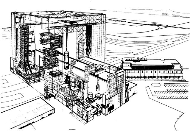
In designing a building that was to have an enclosed volume of 3.6 million cubic meters (almost as much as the Pentagon and the Chicago Merchandise Mart combined) and an area of 32,000 square meters, URSAM faced a challenge. By using a simple box shape, the designers could obtain a strong building at minimum cost. Further, they could eliminate the need for separate cranes for each bay by putting a transfer aisle between the high bays. The boxlike layout of the building, 160 meters high, 218 meters long, and 158 meters wide, allowed for an individual door and passageway from each high bay to the crawlerway.12 According to Anton Tedesko, the following factors influenced the layout and structure: “stiffness against windloads, adaptability to changes, ease of connection with future extensions (planning included provisions for a 50% increase in assembly capacity to accommodate six space vehicles), and above all, adequate working space for those who would assemble and check out the vehicles and an efficient arrangement of that working space."13
One of the biggest design problems involved the high windloads that the building would have to withstand. After consulting authorities on wind velocity, URSAM designed the VAB for winds of 200 kilometers per hour. The design had to minimize the building’s sidesway, because the work platforms in the high bays were tied into the structure. If the building swayed in high winds, the resulting movement of the platforms might damage a space vehicle. Although the box shape was not the most effective in shedding wind, it kept the sidesway low. The final design held the building’s sway to less than 15 centimeters in winds up to 100 kilometers per hour. In higher winds the platforms would be withdrawn from the vehicle.
The designers had to accept certain operational penalties to achieve the required stability at reasonable cost. One of the most apparent was the 58-meter-high framework along the transfer aisle. This framework took 65% of the load from winds blowing parallel to the aisle (north-south), but restricted the passage from the transfer aisle to the high bays. Crane operators would have to lift the first stage up and over the framework to place the booster on a mobile launcher in the high bay.14
Since launches from the pad, 4.8 kilometers away, would subject the building to heavy shock waves and acoustical pressures, more than 100,000 square meters of insulated aluminum panels fastened to steel girders would be used to protect the structure on the outside. To create a “sense of airiness in the transfer aisle without admitting a glare or random sunbeams,” URSAM recommended a total window surface of 6,440 square meters provided by 1.2 by 3.7-meter impact-resistant, translucent plastic panels.15
The size of the building and height of the high bay areas presented other unique problems. Three major ones were the design and development of the atmospheric control system, the high-bay doors, and the lifting devices within the building. To provide proper distribution of air inside the building and to prevent condensation, the designers proposed a forced-air ventilation system with blowers at the top of the low bay and exhaust openings at the bottom. Large gravity ventilators in the roof of the high bays would pass sufficient air to replace the entire high bay volume at least once an hour. In order to maintain a comfortable temperature in the office, laboratory, and workshop complex situated within the low bay area, the designers planned a 9,000-ton-capacity air conditioning system sufficient to cool 3,000 homes.16 In addition, by using its standby capacity this system would cool the space vehicle and base section of the mobile launcher. Self-contained units would cool individual platform levels in the high-bay section.
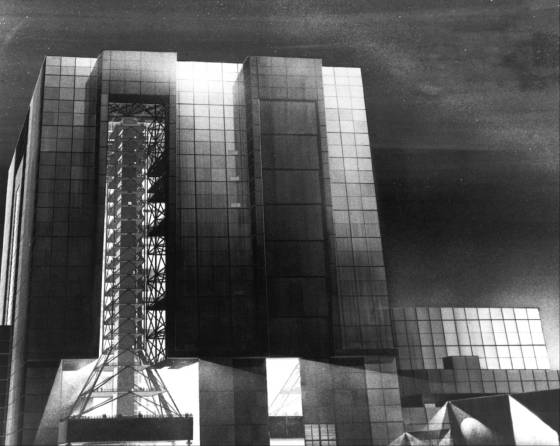
The selection of the proper doors to protect the inside of the VAB required much thought. The mobile launcher would enter and leave a high bay through an opening 139 meters high. The opening, shaped like an inverted T, would measure 45 meters wide at the base and 22 meters at the top. The designers settled upon a plan with seven leaves covering the top part of the opening. These leaves, 22 meters wide and 15 meters high, would lift vertically and sequentially to be stacked at the top of the opening. Four motor-driven leaves, among the largest doors ever placed on a building, would slide horizontally to cover the bottom 35 meters of the high bay opening. The eleven leaves weighed from 29 to 66 metric tons; opening them took nearly an hour.17
Initially there was concern about some of the VAB’s lifting devices. Operational requirements called for a 250-ton bridge crane with a hook height of 141 meters that could span a distance of 45 meters. The large crane and its support in the upper reaches of the VAB posed a weight problem for the foundation. As the design progressed, however, this problem disappeared - the foundation and structural strength required for the anticipated windloads provided ample support for the cranes.18
Design studies of the building’s foundation included wind-tunnel tests of a model and a pile-test program. The latter was initiated under an URSAM subcontract by the C. L. Guild Construction Company in January 1963. Using a sonic hammer, the Guild Company tested the one-meter limestone shelf that lay 36 meters below the surface of Merritt Island and about 12 meters above bedrock. From the results of the wind-tunnel tests and bore samplings, URSAM engineers decided to rest the massive building on a bed of steel pipe piles, each 41 centimeters in diameter. The 4,225 pilings, when driven down to bedrock, would total 205 kilometers of steel pipe. In addition the design called for 38,200 cubic meters of concrete as pile caps and floor slab.19
During the development of the design, URSAM representatives met regularly with individuals from the Corps of Engineers and the Launch Operations Center. Changes in equipment were frequent, and some of them meant changes in the design of the huge VAB. A change in the dimensions of the mobile launcher, for instance, represented a large - and welcome - weight reduction for the launcher, but also required a major change in the VAB doors.20 Colonel Alexander urged the URSAM personnel to keep their counterparts in the Corps and the Launch Operations Center acquainted with daily progress and insisted that careful notes be kept on all intergroup discussions. The Facilities Office promised to deliver the final design instruction on 7-8 March 1963. Bidgood wrote: “The design must be frozen at this time to meet the design schedule and the subsequent construction schedule."21
Notwithstanding Bidgood’s vigorous efforts, modifications of the space vehicle continued to cause problems for the VAB designers. In March, he noted that a recent change had undone 48 sheets of drawings. Shortly thereafter the Manned Spacecraft Center decided to transport the spacecraft in vertical attitude from the operations and checkout building to the VAB, a change that required more height in the low-bay doors. Bidgood refused to adjust the design schedule, stating that “delays in completion of final design as a result of this additional requirement are not acceptable.” As late as 27 June, it was discovered that a required platform for S-IC intertank access was omitted from the design. Finally on 3 July 1963, the design agency notified R. P. Dodd, chief of the Design and Engineering Branch, LOC, that no changes or additional requirements could be permitted except as an amendment during the bidding period.22
URSAM forged ahead despite all the changes, drawing upon the technical capacity of the four constituent companies as the need arose. When key men had to leave, as three did during the course of the year, replacements were easily recruited. Initially the design chiefs relied on manual calculations for the basic designs, using computers to solve some equations. As their confidence increased, URSAM engineers came to rely more extensively on electronic computations. The task was completed and approved on schedule - 23 September 1963.23
The original selection of URSAM had not won unanimous approval. When the combine had almost completed its work, a June 1963 article in the New York Post criticized the choice on the grounds that the Moran firm had designed the Air Force’s $21-million Texas Tower that collapsed off the New Jersey coast in January 1961. In a report to Administrator James Webb on 13 June 1963, R. P. Young, executive officer at NASA Headquarters, discussed the matter at length. He admitted that many deficiencies had shown up in the tower, not all of them related to Moran’s design; but in the URSAM combine Moran was working in foundation design, and the firm was “outstanding in that field.” Young went on to explore the entire matter of the URSAM contract and the design, which he had discussed at length with Gen. Thomas J. Hayes III, assistant to the Chief of Engineers for NASA Support, who insisted that the Corps had made “a careful and straightforward selection of what they considered the best group of firms to do the job, and they know no reason at this time to believe differently.” Hayes also pointed out that the Corps had selected the firm of Strobel and Rengved to make an independent review of structural design; the firm had often worked with the Corps in this capacity before. Hayes admitted the concern engendered by the newspaper article, but noted that a number of competent individuals had reviewed the work and gone away satisfied.24
Launch Control Center Design
URSAM also designed the launch control center, which presented far fewer problems than the VAB. The Manned Space Flight Management Council established ground rules for the design of the building in a meeting on 22 June 1962. Originally, the launch control center was to be placed at ground level in the western section of the low bay of the VAB. In October 1962, a suggestion to place it on the roof of the high bay held up the planning. An URSAM estimate that locating the center on the roof of the high bay would mean an additional expense of $1,200,000 ended the discussion. The structure was built on the southeastern side of the VAB with a long hallway connecting the two. The original plans called for a steel structure, but the structural engineers recommended concrete as better for acoustical purposes, and the final choice was a 114 × 55-meter, four-story, monolithic, reinforced-concrete building that made extensive use of precast and prestressed elements.25
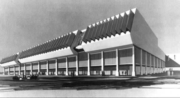
The architects wanted the launch control center to be symbolic. The VAB was to be the factory, and the control center was to be man’s window for observing events projecting into the future. The four multilevel firing rooms were rectangular in shape, 28 meters in width and 46 meters in length. Since many checkout requirements were still unknown, the planners emphasized flexibility, eliminating all columns and providing removable floors.26
The design of the windows shut off the sounds and pressures of the outside world. Two-centimeter-thick glass windows with adjustable sun visors in special aluminum frames faced the launch area. Infrared lamps outside the windows prevented fogging. The tinted, laminated windows, which covered an area 24 meters long and 7 meters high, filtered out heat and glare, permitting only 28% of the light to enter the room. Transparent glass, separating a viewing section from the rest of the firing room, gave guests a feeling that they were part of the operation. For its efforts on the launch control center, URSAM won the 1965 Architectural Award for the industrial design of the year.27
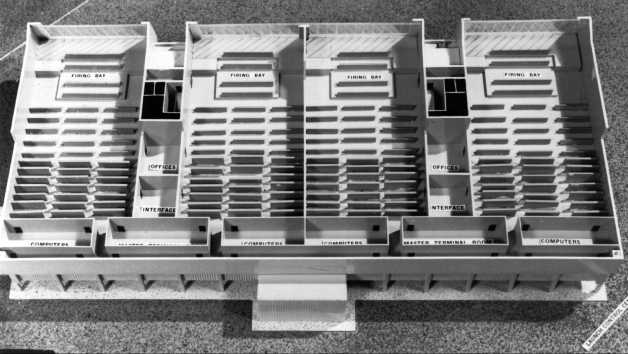
While URSAM was designing the buildings, LOC engineers were determining what equipment would go inside. The control center’s display stations were initially projected at a 13 September 1962 meeting between LOC representatives and Huntsville’s Astrionics Division. Display consoles would monitor such things as propulsion, navigation, measuring, ordnance, propellant loading, ground support equipment, and emergency detection. Rack requirements included countdown clock, TV and communications, and discrete recorders. Criteria for the ten consoles located in each firing room for the control, test, and monitoring of the mobile launcher’s electrical support equipment were furnished by the Launch Support Equipment Engineering Division. The design and fabrication of the panels were the responsibility of the Astrionics Laboratory at Marshall.28
During the following year, the emphasis shifted from a systems-oriented firing room to one organized by flight stage or hardware. Nearly 450 consoles would be operated by representatives from the stage contractors and Radio Corporation of America, General Electric, Saunders, Symetrics, International Telephone and Telegraph, NASA, and the Eastern Test Range. The consoles were arranged to permit the Boeing, North American, and other teams of engineers to sit together in their respective stage groupings. Responsibility for designing the consoles rested primarily with the various companies, but the designs were coordinated by LOC. W. O. Chandler, Jr., Deputy Chief of the Electrical Systems Branch, recalled making at least 25 trips to Houston and other Apollo offices to make certain that design change information for the consoles was current.
Design of the Crawlerway
While men had moved two- and three - story houses often enough - even some from Merritt Island to the mainland of Florida - no one had ever before moved a skyscraper. Yet that is what the mobile concept called for - or at least an Apollo-Saturn vehicle the size of a skyscraper. The problem was compounded by Merritt Island’s marshy terrain and high winds. The combined weight of the crawler-transporter carrying the mobile launcher would exceed 7,700 tons. No one knew what effect such a load would have upon the subsoil of Merritt Island. C. Q. Stewart of the Mechanical Engineering Division had commented on this problem in a memorandum of 1 August 1962 and suggested exploratory borings. He also spurned any type of rigid surface for the crawlerways as too prone to cracking, and urged instead a topping of gravel or crushed stone.29
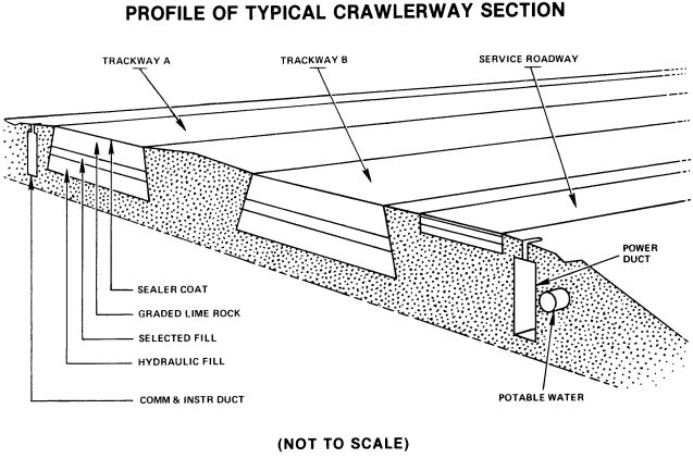
On 1 February 1963, two months after the signing of the URSAM contract, the Detroit firm of Giffels and Rossetti agreed to design the crawlerway and the pads. Three weeks later 19 individuals representing NASA, the Corps of Engineers, and various contracting firms gathered at the LOC for a crawlerway conference. URSAM proposed building the crawlerway of layers with a total thickness of 1.4 meters, topped by crushed stone and a soft grade of asphalt. The Corps of Engineers agreed to compact sand to a depth of 7.6 meters below the pavement by vibroflotation in the areas adjacent to the VAB.30
At another meeting at the Cape on 27 March 1963, representatives of Giffels and Rossetti discussed the crawlerway with representatives of NASA, URSAM, the Corps of Engineers, Marion Power Shovel, and Brown Engineering Company. Donald Buchanan of LOC and one of the Marion representatives objected to the proposed use of an asphalt surface for the crawlerway. They feared that the asphalt would adhere to the treads of the crawler-transporter and cause severe wear of the road surface. The conferees then established two criteria for selecting materials: the surface material should not adhere to the crawler’s treads and the coefficient of friction of the materials should not exceed 0.3 under the expected operating temperature range.31
During the next few months there were more meetings, one in Jacksonville on 27 June, another in Detroit on 14 August. At the former the Marion Power Shovel representative discussed the limits of friction. The conferees determined that the crawler would break up any type of hard surface, and the best surface would be crushed stone - as Stewart had suggested a year before. After the latter meeting, J. B. Bing of the LOC programming office reported that there had been absolutely no coordination between Giffels and Rossetti and URSAM, even though their respective areas of design had an obviously close relationship.32
In the fall of 1963, eight representatives from LOC and the Corps of Engineers formed the “Construction Coordination Group for Complex 39”; the group’s purpose was to manage the details of construction at the launch complex. The chairman briefed members on the construction status, problems, delivery of materials, and the impact of each change on critical construction schedules and contract costs. The scope of the group’s work included scheduling, processing of changes, quality requirements, and funding. The Construction Coordination Group commenced operation immediately and was to continue until the completion of major Corps construction on complex 39.33
Flame Deflector and Launch Pads
If any one item virtually dictated the design of the launch pad, it was the flame deflector. This device would send the fiery exhaust of the five firststage engines along the flame trench. The LOC designers who established criteria for the pads had wanted to keep the Saturn vehicle as close to the ground as possible in order to lessen wind stresses. They settled on a two-way, wedge-type flame deflector similar in design to those used on pads 34 and 37. The deflector, 13 meters in height and 15 meters in width, would weigh 317 tons. Since the water table was close to the surface of the ground, the criteria group wanted the bottom of the flame trench at ground level. The flame deflector and trench determined the height and width of the octagonal shaped launch pad; this in turn set the width of the space between the crawler treads, because the crawler straddled the pad.
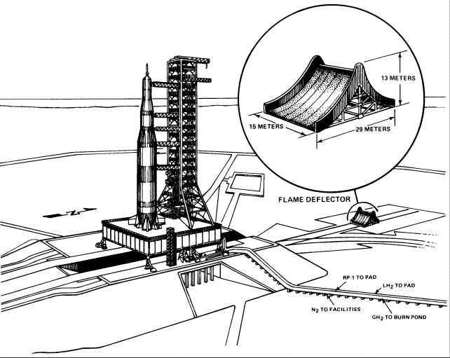
During the last week of June and throughout July and August 1962, tests on 1:58 scale-model flame deflectors were conducted by the Test Division and Aeroballistics Division at Huntsville. They found that the launch complex 37 deflector, a copper, water-cooled, ridged model, suffered serious erosion from the concentration of heat and high gas velocities. By March 1964, the preliminary designs for a steel deflector and for a reinforced concrete deflector had been completed. By means of instrument readings and motion pictures, the aerothermodynamic flow characteristics were determined, and the flame deflector and trench designs were refined. In designing the deflectors for launch complex 39 pads, it was necessary to have a replaceable leading edge which eroded but was insulated. Four types of deflector ridges were tested, using information gained in the study of heat-resistant shapes and materials for the Jupiter-C nose cone. When sufficient evidence was gathered, the design of the deflector proceeded with dispatch.34
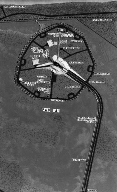
The design of launch pads A and B presented further difficulties, many of which concerned the slab that covered the pads. This hardstand had to support the crawler-transporter and its pressure of 50 tons per square meter. Under a new proposal, a cellular construction, something like orange crates set in two rows, would support and protect the area adjacent to the flame deflector trench and beneath the crawler. The cellular construction, extending the full length of the flame deflector pit on either side, would provide an explosion buffer to the main launch facilities, reduce the pressure on the launch pad foundations, and offer additional space for service items.35
The selection of a refractory surface for the walls, floor, and an area outside of the flame trench was exacting. Such a surface had to withstand temperatures of 1,922 kelvins and flame velocities four times the speed of sound. Special refractory fire bricks were held to the walls by interlocks, mechanical anchors, and a modified epoxy cement. All concrete surfaces protected by the brick had to have a smoothness tolerance of 0.3 centimeters in 3 meters to provide a bonding surface. This careful work was to limit the maximum temperature in the adjacent concrete structure during launch to 310 kelvins (37 degrees C).36
Other components of the launch pad that required detailed design studies included the terminal connection room, the environmental control system, the high-pressure-gas storage facility, and the emergency egress system. The connection room, which contained extensive instrumentation facilities for testing during prelaunch and launch phases, and the environmental control system, which maintained the temperatures of the vehicle and compartments prior to launch, were designed to withstand concentrated pressures at any point. These rooms would protect ground support equipment located at the launch pad from heat, vibration, and shock during launch.37
By 1 June 1962, the design concept for the Saturn V propellant loading, high-pressure gases, and associated systems had been established. To use a reliable automated system and eliminate the cost of developing a new one, a modified version of the automatic propellant loading and associated systems used for LC-37 was selected for LC-39. Propellant servicing was controlled from the launch control center. Most of the hardware for the propellant-loading system was located in the terminal connection room at the pad. This room contained separate areas for each propellant and its associated systems. The remote command and display equipment in the control center was connected by an independent digital data transmission link to the hardware at the pad, which in turn was connected to the transporter-launcher and the storage facilities by electrical lines. Consequently, control commands could be initiated from the transporter-launcher, the launch control center, or the terminal connection room at the pad during servicing and checkout.38
Plans for the Industrial Area
The site plan for the industrial area, eight kilometers south of the VAB, was prepared by a joint Manned Lunar Landing Program Master Planning Board made up of NASA and Air Force personnel, and its subordinate joint planning committees for facilities, instrumentation, and communications. The committees had to plan and design facilities during a period when much of the equipment that would go into them was still under development. Yet a comparison of two site plans, one prepared in March 1963, the other in October 1965 after a more careful definition of program requirements, reveals few major changes. Most of the facilities remained as originally planned.39 Some of the credit for this successful planning goes to the Air Force’s contractor, the Guided Missile Range Division of Pan American World Airways. Back in December 1962 Pan American had completed a preliminary master plan for Merritt Island. The projection contained three sections: general plans for the launch area, a description of the Merritt Island industrial area, and detailed plans for the launch area. The Joint Facilities Planning Group, one of the several committees the Air Force and NASA set up, organized a task force to assist in preparation, correction, and development of this preliminary master plan. After the Webb-McNamara agreement, NASA used volume III of the Pan American master plan as a basis for its first plan, published in October 1963.40
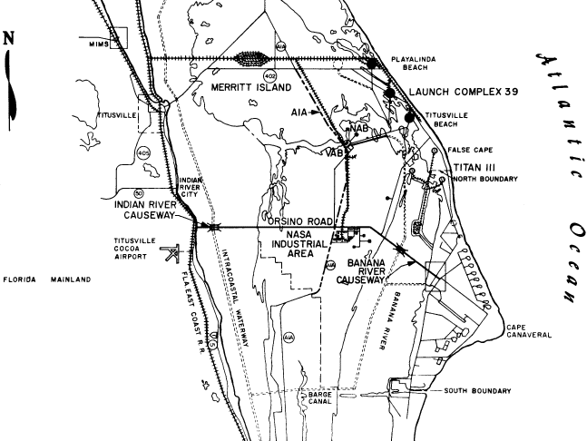
Spacecraft support facilities took up the eastern half of the industrial area. Although the requirements for these facilities and equipment originated with the Manned Spacecraft Center in Houston or with its Florida Operations launch team, the responsibility for planning, siting, funding, and construction rested with the Launch Operations Center. Included among the Apollo mission support facilities were the following:
- Operations and checkout building
- Supply, shipping, and receiving building
- Weight and balance building
- Ordnance storage facility
- Fluid test complex, consisting of:
- Hypergolic test building
- Cryogenic test building
- Environmental control systems building
- Support building
The operations and checkout building was as essential to the spacecraft as the vertical assembly building was to the launch vehicle. The operations-building would be used for the checkout of all non-hazardous systems in manned spacecraft. It would also provide space for the inspection of the spacecraft modules upon arrival at KSC, and for the mating and final integrated tests of the Apollo before it traveled to the VAB. Accommodations for astronaut preflight activities (living quarters, a technical and briefing area, a crew preparation area, and a bio-medical area) were included in the building. The floor area, 27,900 square meters, was divided into four functional areas: an administrative and engineering office area with an auditorium and cafeteria; a laboratory and checkout area with automated checkout equipment and data reduction and display facilities; a high-bay assembly and test area having a bridge crane hook height of 36 meters and a contiguous low-bay area with a crane hook height of 15 meters; and a service area containing shop space, a tool room, spare parts room, and space for electrical, mechanical, and vacuum equipment. The building was air conditioned and, where operationally necessary, humidity controlled and dust free.
Although it was always intended that the spacecraft modules (and the launch vehicle stages) would arrive at LOC in a flight-ready condition, the mechanics of shipping and the checkout process itself required that certain spacecraft parts be packed separately. Inevitably in the course of testing, some components had to be replaced, and those removed had to be returned to their makers for repair or modification. Also, various items of ground support equipment associated with the checkout and assembly processes were shipped with the spacecraft. The supply, shipping, and receiving building would provide the space for these functions. It was a one-story, L-shaped building of standard construction, with approximately 3,720 square meters of floor area that included a machine room, a roofed-over loading dock, shipping and receiving and supply departments with a humidity-controlled storage area, a ground support equipment area, and cleaning, painting, carpentry, maintenance, and plastic shops.
The Planning Board isolated the facilities with hazardous operations in the southeast corner of the industrial area. KSC personnel frequently referred to the area located over a kilometer from the operations and checkout building as the “south 40.” The facilities there included the weight and balance building, the ordnance storage building, and the fluid test complex. At the north end of the area was a 300-meter range for testing the rendezvous radar on the lunar module.
After checkout in the operations and checkout building, the spacecraft was to be moved to the weight and balance building, where the launch team would install solid-propellant motors, the launch escape tower, and various pyrotechnic items. After weighing and balancing the assembled spacecraft to determine its center of gravity, technicians would optically align critical components. Here, also, the spacecraft would receive its final servicing prior to departure for the VAB. The building would consist of a high-bay area having an overhead crane with a hook height of 30 meters and two adjacent low-bay areas. A door, of sufficient height and width to accommodate the assembled spacecraft in a vertical position, would take up almost all of one side of the building.
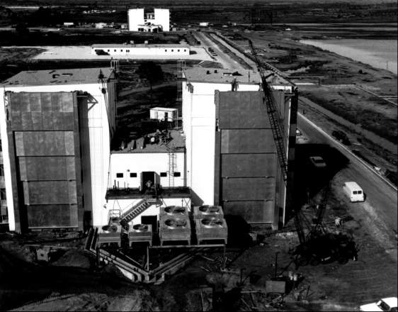
Contained under pressure in the spacecraft were environmental control, hypergolic, and cryogenic systems, all of which used corrosive and highly combustible fluids. Careful handling was obviously required. Because of the hazards in testing, adjusting, and verifying the proper operation of these systems and their component parts, and because the test methods were somewhat similar, the several buildings where these operations would be performed were grouped in the fluid test complex. The test buildings differed in size, but were similar in form. Each contained one or two test cells equipped with high-capacity exhaust systems, a floor system for collecting and diverting spilled fluids, and fire extinguishing systems. Adjacent to the test cells were control rooms designed and constructed to protect test operators from explosions or toxic fumes. An equipment storage room, dressing or locker rooms, and machinery rooms were included in each test building. Nearby was a support building containing offices, shops, and laboratories. It was air conditioned and equipped with a special filtering system to provide clean conditions in the laboratories. Miscellaneous service facilities for the test complex included stations for the parking of mobile fluid transfer tanks, and a dilution system and disposal dump for spilled fluids.
The ordnance storage building, slightly less than 370 square meters in floor area, would provide an environmentally controlled storage area for solid-fuel motors and aligned escape towers. This was designed to prevent any deterioration of explosives that could result in a misfire in space.41
Design of the Central Instrumentation Facility
Under the terms of the Webb-McNamara agreement, LOC was given certain instrumentation responsibilities on Merritt Island. Debus assigned these to Karl Sendler, the Director of Information Systems; and FY 1964 construction of facilities budget estimates for launch instrumentation reflected the new management.42 Subsequent agreements concluded by Debus and the Missile Test Center clarified the instrumentation program and established a Joint Instrumentation Planning Group as the local coordinating body.
The systems planned for installation in the central instrumentation facility were based upon those developed during Saturn I operations at complexes 34 and 37. The instrumentation systems criteria group held numerous meetings with design and operations personnel to determine what measurements were needed. Experience with LC-34 and LC-37 was of limited value, however, because the distance from LC-39 to the control center was more than 14 times as long. After the criteria had been established, fixed-price contracts were negotiated. The digital acquisition equipment was designed by Scientific Data Systems; the computer was the GE 635. Since the number of on-board measurements for the vehicle had increased from 200 to 300, it was necessary to procure equipment that produced accurate data in real time. For this type of instrumentation, there was no inhouse design, but the specifications were assembled and bids were solicited from industry.43
By May 1963 the design criteria for the central instrumentation facility were available. The building - a three-story structure of approximately 12,480 square meters just west of the headquarters building - would house computers and other electronic equipment for reduction of telemetry data, analysis, and transmission to other NASA centers. A smaller building, later known as the CIF antenna site, was placed 2.5 kilometers north of the industrial area, to be free of radio-frequency interference and have clear lines of vision to the NASA launch complexes.44
The central instrumentation facility reflected the desire of Karl Sendler and his planners to centralize the handling of NASA data and provide housing for general instrumentation activities that served more than one complex. LOC coordinated the planning with the other NASA centers and with the Atlantic Missile Range. It was necessary to ground all metal in the structure and to ground separately the commercial power and the instrumentation power systems. Fluorescent lights were not permitted - they cause electromagnetic interference. When completed, the central instrumentation facility, with disc-shaped antennas adorning the roof, would be the most distinctive building in the industrial area.
Selection of MILA Support Contractors
While the design of LC-39 and the industrial area was still under way, LOC sought contractors who would operate and maintain the Merritt Island facilities. On 22 April 1963 LOC suggested four possibilities to Albert Siepert, NASA’s Director of Administration in Washington, who would soon join LOC’s management:
- Extension of the current Air Force contract with Pan American Airways to provide services for Merritt Island similar to those being provided for Cape Canaveral’s Missile Test Area.
- Employment of a single NASA support contractor to provide all services.
- Employment of several contractors, each to perform a major function under direction of NASA staffs.
- Expansion of the LOC civil service staff.
LOC recommended the third solution, with 12 functional contractors.45 Earlier that month, Siepert and Brainerd Holmes had discussed the launch center’s need for support services with Robert Seamans, NASA’s Associate Administrator. Seamans turned down an Air Force proposal to handle the entire service support through its range contractor, Pan American. Seamans wanted to spread contracts and did not want to increase civil service hirings. He favored the use of four or five prime contractors.
One week after the LOC staff report, Debus and Siepert met with Holmes in Washington. LOC recommended seven contracts with a separate food service contract handled by the NASA Employees’ Exchange. Holmes thought seven contracts were too many for effective management and directed that LOC find a way to compress these into four. He did agree, after some discussion, that the food service could be a separate contract under the Exchange. LOC submitted a revised proposal on 7 May including a request that “LOC be authorized to initiate appropriate action to obtain contractor services. . . , grouped into four prime areas of activity. . . .” Holmes approved it two weeks later.46
As a temporary measure, NASA asked the Air Force for limited Merritt Island support services on a reimbursable basis. This was formalized as part of an interim agreement on management responsibilities signed by Dr. Debus and General Davis on 10 May 1963. Two weeks later, NASA Headquarters announced contract plans for more than 20 support functions in the four areas of management, communications, base support, and launch support. The prime contractors would be required to subcontract a substantial portion of the work to small firms.47
LOC’s procurement office started work on one contract a week before the formal announcement. A request for proposals on the operation and maintenance of the communications system was issued 17 May. Contractor interest was heavy, but a disagreement between LOC and Southern Bell Telephone Company about interconnection points between the internal communication system and the Bell circuits delayed contract negotiations for over a month. Finally Southern Bell agreed to provide normal internal business and administrative telephone service (excepting service in hazardous or operationally critical areas). NASA Headquarters decided that source evaluation boards were necessary. Fourteen companies responded to LOC’s second request for proposals. Administrator Webb narrowed the field to three firms, following an evaluation board presentation on 3 October. R.C.A. Service Company won and began work in December, although execution of the cost-plus-award-fee contract was delayed until mid-January 1964.48
Procurement action on the other three support contracts proceeded concurrently. A January 1964 cost-plus-incentive-fee contract gave Ling-Temco-Vought responsibility for photographic support, technical information, a field printing plant, and administrative automatic data processing. In February 1964 Trans World Airlines won the contract for supply, general maintenance, and utilities. In April, Bendix Field Engineering Corporation signed a contract for a variety of functions that included propellant services, precision shops, high-pressure-gas converter and compressor operations, cryogenic-equipment cleaning, spacecraft servicing facilities, and the operation of the crawler.49
ENDNOTES
- In this section the authors relied extensively on research by William Lockyer, Jr., and James Covington.X
- Col. J. V. Sollohub to Debus, 15 Oct. 1962.X
- “To Design for the Moon Age, Four Firms Work as One Team,” Engineering News-Record 172 (6 Feb. 1964): 46-48.X
- Alexander interview; Anton Tedesko to Urbahn, Knecht, and Rutledge, 10 Aug. 1962.X
- URSAM, “VAB-LC39: Report of a Meeting with Representatives of LOC, Corps of Engineers and Component Contractors,” Cape Canaveral, FL, 28 Aug. 1962.X
- Ibid., pp. 2-6.X
- Wesley Allen, Brown Engineering Co., memo for record, “Meeting with Facilities and MSC,” 17 Sept. 1962.X
- Bidgood to Poppel, 26 Sept. 1962.X
- Col. Wm. Alexander, “Report on VAB,” undated, p. 5; J. Bing to R. P. Dodd, 7 Nov. 1962; Theodor A. Poppel to Bidgood, 21 Nov. 1962; and Gerstenzang and Carraway to Dodd, 23 Nov. 1962.X
- William D. Alexander, “Vertical Assembly Building - Project Description, Organization, and Procedures,” Civil Engineering 35 (Jan. 1965): 42-44.X
- Ibid., p. 44.X
- Gerald C. Frewer, “Kennedy Space Center - Assembly Line on a Gigantic Scale,” The Engineering Designer, May 1967, p. 7.X
- Anton Tedesko, “Base for USA Manned Space Rockets (Structures for Assembly and Launching),” International Association for Bridge and Structural Engineering Publications 26 (May 1971): 535; Tedesko, “Design of the Vertical Assembly Building,” Civil Engineering 35 (Jan. 1965): 45-49.X
- Anton Tedesko, “Space Truss Braces Huge Building for Moon Rocket,” Engineering News-Record 172 (6 Feb. 1964): 24-27.X
- James H. Deese, “The Problem of Low Level Wind Distribution,” paper presented at the Structural Engineers Councils of Florida, First Annual Conference, Tampa, 9 Nov. 1964.X
- Kurt Debus, “Some Design Problems Encountered in Construction of Launch Complex 39,” paper given in Darmstadt, Germany, 25 June 1964; R. P. Dodd, “HVAC Temperature Control System for VAB and LCC,” with attachment, “VAB HVAC Temperature Control System,” 14 July 1963; G. J. Burrus, LCC and Sup. Fac. Sec., memo for record, “LCC Air Conditioning Unit Reliability,” 28 July 1965.X
- Debus, “Some Design Problems Encountered,” p. 35. Apollo Launch Complex 39 Facilities Handbook, issued by the U.S. Army Corps of Engineers, South Atlantic Div., p. 14, gives different numbers: height of each door opening, 140 meters; lower door opening 46.32 meters wide and 34.74 meters high; upper door opening 23.16 meters wide and 104.24 meters high.X
- Alexander, “Report on VAB,” p. 13; Tedesko, “Design of the Vertical Assembly Building,” pp. 48-49; Dodd interview.X
- Philip C. Rutledge, “Vertical Assembly Building - Design of Foundations,” Civil Engineering 35 (Jan. 1965): 50-52.X
- Alexander, “Vertical Assembly Building - Project Description,” pp. 43-44.X
- Stein interview; Bidgood to Clearman, “Design of the Vertical Assembly Building, Advanced Saturn Launch Complex 39,” 6 Mar. 1963.X
- Bidgood to Mr. Lenezewski, CE Canaveral Dist., “LC-39 Transfer Aisles,” 7 July 1963; Andrew Pickett to Dodd, “Platform Access to S-IC Inter-Tank Area VAB,” 27 June 1963; Dodd to Bertram, “LC-39 VAB and LCC,” 3 July 1963.X
- “Launch Complex 39,” brochure issued by Corps of Engineers for contractors’ conference, Oct. 1963, p. 4.X
- R. P. Young, NASA Exec. Off., to Webb, 13 June 1963.X
- M. Menghini, Field Rep., URSAM, memo for record, “Telephone calls to and from Col. Alexander,” 31 Oct. 1962; Anton Tedesko, “Assembly and Launch Facilities for the Apollo Program, Merritt Island, Florida: Design of the Structure of the Vertical Assembly Building,” paper presented at the ADCE Structural Engineering Conference and Annual Meeting, 19-21 Oct. 1964, p. 10.X
- Stein interview.X
- Brown interview. The NASA-Corps of Engineers movie The Big Challenge confirms Brown’s testimony.X
- D. T. Brewster to W. W. Kavanaugh, “Minutes of Meeting between M-ASTRA and M-LVOD, 13 Sept. 1962,” 31 Oct. 1962; MSFC, “Saturn V Electrical Ground Support Equipment for Launch Complex 39,” pp. 1-11.X
- C. Q. Stewart, Mechanical Engineering, memo for record, 1 Aug. 1962.X
- “Minutes of Crawlerway Design Conference,” NASA-LOC, Cape Canaveral, 21 Feb. 1963.X
- “Minutes of Crawler Transporter Crawlerway Meeting,” LOC E & L Building, 27 Mar. 1963.X
- J. B. Bing, memo for record, 9 July 1963; Bing, memo for record, “Trip Report,” 16 Aug. 1963. In line with the complaint of Mr. Bing, the authors found no reference on the part of URSAM people to Giffels and Rossetti in any of the many articles that appeared on URSAM’s work on the VAB. In an article in Engineering News-Record for 6 Feb. 1964, p. 28, for instance, one of the URSAM principals mentions the companies that constructed the first launch pad and the crawlerway, but not the firm that designed both of them.X
- A. H. Bagnulo to U.5. Army Engineer Dist., Canaveral, 7 Oct. 1963; Lt. Col. Leo J. Miller, Corps of Engineers, Asst. Dist. Engineer, “Construction Coordination Group for NASA-LOC Complex 39,” 14 Oct. 1963; Ernst interview.X
- Launch Support Equipment Engineering Div. Monthly Progress Reports, 10 Oct. 1962, 13 Mar. 1964.X
- J. H. Deese, Chief, Facilities Engineering Sec., memo for record, “Engineering Analysis of Launch Pad Diaphragm Construction, Launch Pad 39B,” 11 Mar. 1963.X
- “Theoretical Analysis of Surface Temperatures, Flame Trench, Complex 39 A/B, KSC,” technical memo 2-62, Mar. 1967, U.S. Army Engineer, Ohio River Div. Laboratories, Cincinnati.X
- Giffels and Rossetti, “Structural Design of Pad Terminal Connection Room and Environmental Control System Buildings,” 11 Apr. 1963, sheet 85; Launch Support Equipment Engineering Div., “Preliminary Release Levels for Ground Support Equipment, Launch Complex 39,” 19 Dec. 1963.X
- Poppel to Petrone, “Policy Statement and Design Concept for C-5 Propellant Loading Systems,” 1 June 1962. A Complex 39 Foundation Prestudy Conference was held on 29 May 1962 at Jacksonville: C. Q. Stewart, memo for record, “Foundation Design Prestudy Conference, Jacksonville DE, 29 May 1962,” 31 May 1962.X
- NASA Merritt Island Launch Area Master Plan, vol. 3, pt. 1, Industrial Area, sec. 1, “General Site Plan,” 22 Mar. 1963. Cf. John F. Kennedy Space Center, NASA, Master Plan, pt. 2, Industrial Area Plans, sec. 1, “General Site Plan,” 25 Oct. 1965.X
- House Committee on Science and Astronautics, Master Planning of NASA Installations, House report 167, 89th Cong., 1st sess., 15 Mar. 1965, p. 24.X
- MSC Florida Ops., Merritt Island Facilities, undated pamphlet describing facilities funded through FY 1963, 1964, and 1965.X
- Dir., Information Systems, KSC, “Project Development Plan for Launch Instrumentatation,” 6 June 1966, p. 2-1.X
- Bruns interview, 22 Aug. 1969.X
- Bidgood to CE Jacksonville, “Central Instrumentation Facility, MILA,” 10 May 1963; B. Baker, memo for record, “Siting of the CIF,” 22 Aug. 1963.X
- LOC Staff Study, Concepts for Support Service at the Merritt Island Launch Area, 6 May 1963.X
- Ibid.; Albert F. Siepert, memo for record, 20 Oct. 1966.X
- 47 “Interim Agreement Implementing the 17 Jan. 1963 Agreement between the Department of Defense and NASA Regarding Management of the Atlantic Missile Range of DOD and the Merritt Island Launch Area of NASA, Part III, Logistic and Administrative Functions,” signed 10 May 1963 by Maj. Gen. L. I. Davis, USAF, and Debus; NASA release 63-111, 23 May 1963.X
- C. C. Parker, LOC Asst. Dir. for Admin., to Debus, 23 May, 5, 19 June, 13 Aug., 9 Oct., 14 Nov. 1963, 8 Jan. 1964; LOC release 74-63, 4 Oct. 1963.X
- Parker to Debus, 18 Sept., 17 Oct., 7, 27 Nov. 1963, 2, 16 Jan. 1964; KSC release 56-64, 24 Apr. 1964.X