New Devices For New Deeds
The Crawler - Transporter
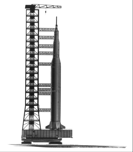
The four unique structures going up on Merritt Island - the vehicle assembly building, the launch control center, the central instrumentation facility, and the operations and checkout building - had their match for distinctiveness in a group of devices being designed and built at the same time: the crawler-transporter, the mobile launcher, the mobile service structure, and the service arms. These novel mechanisms almost defy verbal description, and the reader should refer frequently to the illustrations in this chapter.
Something like the crawler-transporters that would eventually move the Apollo-Saturns from the VAB to the launch pads of LC-39 had been used for surface coal mining in Paradise, Kentucky [see chapter 6-3]. These huge vehicles ran on four tank-like treads, much like bulldozer treads in shape, but considerably larger. One of these double-track mechanisms supported the vehicle at each corner. Since Bucyrus-Erie of Milwaukee was the only firm that had built such giant contrivances, the Launch Operations Center (LOC) sent engineers to inspect them in Kentucky and the Bucyrus-Erie plant in Wisconsin.1 LOC moved toward closing a contract with the Milwaukee firm, as the only company that could build the crawlers in the allotted time. Approval by NASA Headquarters seemed assured.2
Negotiations, however, did not prove so simple. A Bucyrus-Erie employee, Barrett Schlenk, had first interested LOC in using the crawler to carry the spaceship from the VAB to the pad. But when it appeared that Bucyrus-Erie would get the contract under sole-source procurement, William C. Dwyer, Vice President of Marion Power Shovel Co. of Ohio, protested to NASA. Brainerd Holmes urged Debus to use competitive bidding. Twenty two industrial firms sent representatives to a procurement conference, but only two submitted proposals - Marion for 8 million dollars, Bucyrus-Erie for 11 million dollars.3
Now Senator William Proxmire (D., Wis.) protested. Webb met with him and other members of Congress to discuss the matter. Previously, Proxmire had tried in vain to amend the NASA Authorization Bill for fiscal 1963 to require competitive bidding to the “maximum possible extent” [see chapter 8-4]; but now he advanced the cause of a Wisconsin firm, even though it had lost out in competitive bidding. He questioned the validity of Marion’s estimate of an 8-million-dollar cost for the crawler-transporter. Congressman Henry Reuss (D., Wis.) next urged a fixed-price contract to hold Marion to its estimate. But Webb countered that continual modifications would come during construction and insisted on the cost-plus contract.4
A second major factor in Marion’s favor, besides its considerably lower bid, was its announced intention of choosing a project manager from its own personnel, thus saving considerable time in building a team.5 Bucyrus had said it would bring in one from outside. Having received the contract, Marion selected a competent manager, Philip Koehring, not from its own company, but from - of all firms - Bucyrus-Erie. When Marion finally completed the contract two years later, the price had risen above 11 million dollars.
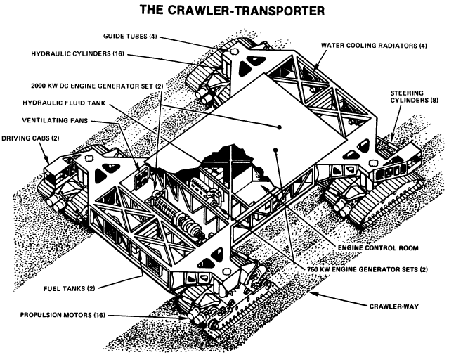
By contract, Marion undertook to assemble the first complete crawler-transporter on Merritt Island by 1 November 1964 and finish road tests, mating, and modifications by 1 March 1965.6 By early December 1963, Marion had completed 90% of the design and promised that parts of the vehicle would begin to arrive at the launch area - now the Kennedy Space Center - in March 1964.7
In the meantime, Marion had run into trouble with one of its subcontractors, American Machine & Foundry, over the hydraulic system for steering and levelling the crawler.8 Balancing a 5,400- metric-ton load called for precision. The motion of the transporter, the height of the load, variations in the level of the roadway , the wind - all would combine to throw the cargo off balance. Marion hired Bendix Corporation to check the levelling and equalization systems on the crawler. The Bendix study, made by mathematician-inventor Edward Kolesa, criticized the levelling systems as too quick and sensitive in their actions. The difficulties between Marion and its subcontractor were not the direct responsibility of KSC. Nevertheless, KSC sent the Bendix study to General Electric for analysis. The GE experts agreed with Kolesa’s calculations.9 As a result, Marion had to adjust the designs. Among other things, a separate power system, distinct from the diesel engines that powered the treads, was added for load-levelling, jacking, steering, and ventilating.
“Prophetically,” said an article in Aviation Week sometime later, “NASA early identified the transporter as the one item which would most likely encounter trouble and whose development, therefore, should be started as soon as possible.”10 One set of problems arose from a factor in Marion’s background. The company had previously held few government contracts and its management lacked familiarity with the intricate procedures and tests that a government contract entailed. Marion had to hire new men to carry out the new procedures, which resulted-in unexpected costs.11
Marion was to have the first of the two units ready for testing in the late fall of 1964, although it was to make its initial trip in April 1965. In the meantime, the monster ran into another snag: someone noted that it had no fire alarm system or fire detection devices. With flammable materials and extensive electronics and mechanical equipment aboard, an alarm system was needed when the crawler was not in use.12 As first designed, the crawler-transporter would carry only dry chemical extinguishers.13
After considerable correspondence during the spring of 1965, the Factory Insurance Association of Hartford made a complete study of fire protection on the crawler. Fifteen recommendations for fire safety included an automatic carbon dioxide extinguishing system for the electrical control room, the entire engine room, and the hydraulic equipment compartment; a limited, automatic sprinkler system as backup protection for the carbon dioxide system; an automatic, total-flooding foam system; flexible water connections to the sprinkler and hose systems in the transporter parking area; meticulous housekeeping and cleanliness inside the crawler-transporter; and the use of 100% noncombustible materials in all future construction and modifications to the crawler-transporter.14 The contractor set about putting in a satisfactory fire prevention system.
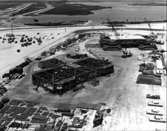

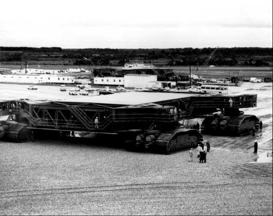
When finally assembled, the crawler-transporter would not have won any awards for beauty. From a distance it looked like a steel sandwich held up at the corners by World War I tanks. Each crawler- transporter was larger than a baseball infield and weighed about 2,700 metric tons. Two 2,750 horsepower diesel engines powered 16 traction motors, which moved the four double-tracked treads. Each tread had 57 “shoes.” Each shoe, 0.3 × 2.3 meters, weighed close to 900 kilograms. Quite naturally, a great deal of experiment and readjustment preceded the final success of such treads. Because of their importance and cost, they were nicknamed, “Them Golden Slippers.” Many people recalled the next line of that song: “Golden shoes I’m going to wear, to walk that golden street.”15 The crawlerway would be such a street.
Building a New Kind of Road
For the safe movement of the crawler-transporter, mobile launcher, Saturn V, and Apollo (a load exceeding 8,400 metric tons), engineers would have to design a unique roadbed. The completed crawlerway would look something like the many interstate highways under construction throughout the nation in the 1960s. Beyond surface appearance, however, the resemblance ended. The crawlerway would support loads never envisioned for a public road-loads in excess of 58,000 kilograms per square meter.16
Gahagan Dredging Company had already begun preliminary site preparation. After excavating softer, unsuitable surface material, Gahagan had pumped nearly 2.3 million cubic meters of hydraulic sand fill into place on the crawlerway route. Vibratory rollers had compacted this fill under the trackways, and then a 90,600 kilogram vehicle proof-rolled them.
Each of the dual trackways, separated by a median strip, would consist of slightly over a meter of selected sub-base material, topped by a meter of graded crushed aggregate, with a blacktop sealer over all. A service road would border the south side of the crawlerway from the VAB to pad A. Underground ducts for communication and instrumentation lines to link the control and assembly areas with the launch pads would parallel the north side of the crawlerway; power line ducts and a pipeline for drinking water would go along the south side. Where any of the ducts or pipes had to pass beneath the crawlerway, the access tunnels had to be capable of withstanding the load conditions. The completed crawlerway would be level with the terrain, 2.3 meters above sea level.
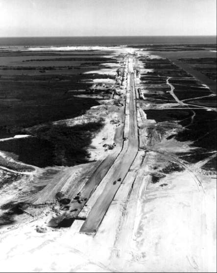
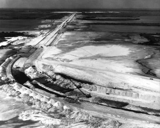
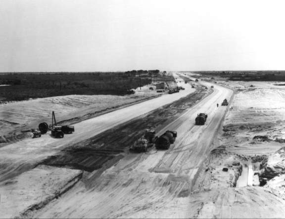
Two firms, the Blount Brothers Construction Company of Montgomery, Alabama, and the M. M. Sundt Construction Company of Tucson, Arizona, acting jointly, agreed to build pad A and the crawlerway for $19,138,000, somewhat under the estimated cost of $20,000,000. Blount-Sundt started work on 19 November 1963. The contract called for the construction of about 5,500 meters of crawlerway from the VAB to launch pad A, the elevated pad, several related facilities in the pad area, and the parking site for the tower. Subsequently a high-pressure-gases converter-compressor facility was added to the contract, at a cost of $155,000. The converter-compressor facility was to be complete on 1 May 1964, the arming tower (mobile service structure) parking site by mid-May, the crawlerway ready for test by 1 November, and the overall project by 1 June of the following year. The George A. Fuller Company of Los Angeles signed a contract on 30 November 1964 to construct pad B and extend the crawlerway 2,100 meters. Using experience gained by Blount-Sundt, the Fuller personnel were well on their way with their work by the middle of 1965.17
The converter-compressor facility was built just north of the crawlerway, about one-third of the distance from the VAB to pad A. It consisted of a one-story equipment building and a 1,892,000-liter spherical tank for storing liquid nitrogen, together with an access road and paved parking areas. A railroad spur brought tank-car loads of helium and nitrogen to the facility. Its evaporators, compressors, and pumps, in turn, supplied high-pressure gaseous nitrogen and helium to storage and distribution facilities at the VAB and the launch area.
Since plans called for the construction of the mobile service structure on the parking site, this facility would have to support considerable loads. The service structure would weigh 4,763 metric tons. When the crawler- transporter moved beneath it, the total load on the parking position would be nearly 7,500 metric tons, heavier than the USS Halsey, a guided missile frigate. In addition to this, calculations showed that, should wind velocities reach 200 kilometers per hour, the service structure, standing by itself on its four support legs in the parked position, with side struts and hold-down arms for each leg, could exert about 6,300 metric tons of force. To withstand these anticipated forces, the parking site had to have a heavily reinforced base.
The Swing-Arm Controversy
The most difficult of all launch mechanisms to describe verbally is the mobile launcher, at times called the launch umbilical tower. It consisted of three main features: a two-story platform 49 meters long by 40 meters wide, on which the launch vehicle stood both on the crawler-transporter during its journey from the VAB to the pad, and on the pad itself, held erect by four hold-down arms; a tower that resembled the Apollo-Saturn in shape and size, and stood beside it surmounted by a hammerhead crane; and, attached to the tower, nine swing arms of various sizes that carried electric, propellant, and pneumatic lines to the space vehicle. These swing arms would automatically move away from the vehicle between the time of ignition and liftoff. The two-story launch platform housed computers that were connected to the launch control center. The platform also had a 14-meter square opening in the center for the rocket exhaust. Two high-speed elevators were centrally located in the tower. Besides their ordinary function of bringing personnel and equipment to various levels, they formed part of an emergency egress system.18
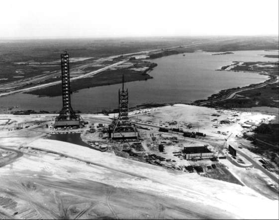
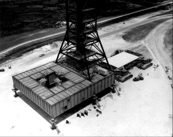
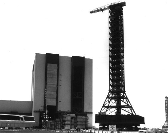
The Jacksonville-based firm of Reynolds, Smith, and Hills designed the tall mobile launcher that replaced the umbilical towers previously used at the Cape. Ingalls Iron Works of Birmingham, the prime contractor for steel erection, began work on the first launcher in December 1963. Nine months later workers hoisted the last major piece of steel, a 19-ton crane boom, into place on the first mobile launcher. The crews proceeded to outfit the finished tower with ground support equipment and electrical apparatus. They expected to have the giant completed in another 12 months.19 In February 1965, Ingalls topped out the second tower, and on the afternoon of 1 March of the same year topped out the third (and last) with the hoisting of its huge hammerhead crane to the top of the 136-meter structure.
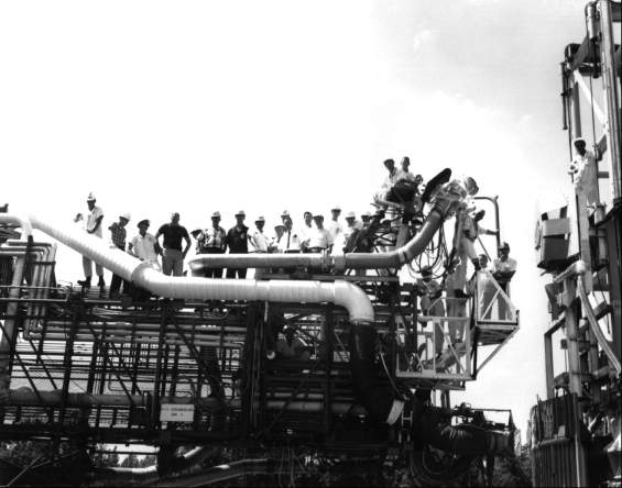
In planning and building the mobile launcher, the most difficult features were the nine swing arms, or service arms, as they were also called. The Brown Engineering Company of Huntsville, Alabama, designed the service arms in conjunction with Theodor A. Poppel’s Launch Support Engineering Division. Brown faced unusual problems: the equipment was novel - no one had built such large access and umbilical devices in combination before; the vehicle for which the swing arms were being designed was developing so fast that the criteria changed continually, even after NASA had let the contract for construction; and the service arms were to be amazingly complex pieces of equipment. By way of example, as many as 24 electric cables, each 50 millimeters in diameter, and about 44 fluid service lines, ranging from 12 to 25 millimeters thick, went into a single umbilical carrier. Each arm would be wide enough for a jeep to drive across - though none ever was to do so. Their length varied with the configuration of the vehicle; they would average over 22 metric tons in weight.20
Employing 250 people on the project, Brown Engineering made 5,000 drawings and 11,000 pages of specifications, but NASA designers found many unsatisfactory features. The company admitted errors in the drawings - but not in numbers or significance out of proportion to the average error rate for such a complicated enterprise. In retrospect, Cliff Boylston, the design project engineer for Brown at the time, was to agree with individuals at KSC that “one typical arm should have been totally tested before going into production.” Boylston concluded that the “design was started before the criteria were set.... The developmental effort was not complete before the production started.... [In spite of this] we gave the customer the best effort that he could have gotten anywhere in the time, and within the limitations we had on us....21
Boylston was correct in saying that NASA had not developed a prototype of an entire service arm. As early as 30 July 1963, however, William T. Clearman, head of the Apollo-Saturn V Systems Office, had authorized a prototype within the allowable funds and schedules.22 Before the end of June 1964, NASA had built and tested a partial prototype of arm 6 - a typical one that included all critical aspects. Contemporary photographs of the prototype compare favorably with the final version of service arm 6.23
When NASA opened bids on the service arms on 31 July 1964, the low bidder was Hayes International Corporation of Birmingham, Alabama. A pre-award service team made an on-site inspection of Hayes. The following day Raymond Clark, in charge of the team, reported: “Past experience with sub-standard quality from Hayes, under previous contracts, along with the results of this survey, may dictate an evaluation of Martin-Baltimore.” Debus penned a note on the bottom of this statement: “This is in conflict with what you told me."24 The service team concluded that Hayes had the personnel to do the job, but needed additional facilities and tools and would have to incorporate into their plans further recommendations of the survey team. It seemed that Hayes had built up a good team in earlier years, but had lost many of its better men during a time it had fewer contracts. On 25 August the Launch Support Equipment Engineering Division expressed serious reservations about Hayes’s technical capacity to perform the task. Yet during the previous week, the Division had changed several hundred drawings, which would have strained the capacities of any bidder.25
In spite of these misgivings, the contract went to Hayes International on 10 September 1964, with a fixed price of $11,480,113 and a completion date of 26 April 1966.26 At this time, incidentally, KSC was under pressure from the Office of Manned Space Flight to contract every possible item by fixed price competitive bidding. The fixed price contract, however, soon proved untenable. The details of the service arms were in a state of constant change, and a fixed price contract is valid only for a fixed design. The arms were a new design, more complex and mechanically larger than those used on the Saturn I.27
Shortly after Hayes International started work, it “uncovered innumerable discrepancies in the design and bills of material.” Hayes notified the KSC Procurement Division that although it had believed it had a complete document package, many drawings were missing or tentative. On 27 October, Procurement delivered to Hayes less than 100 missing drawings. Ultimately, however, drawing changes for all reasons, including research and development, went above 4,000.28
To alleviate these problems, in late November 1964 the Apollo-Saturn V Test and Systems Engineering Office of KSC’s Apollo Program Management Office concurred with the recommendation of Procurement Division’s Launch Support Equipment Section to change the contract so as to incorporate revised lists of drawings. These lists would supersede all documentation previously incorporated, including documents attached to the original invitation for bids and subsequent change orders that revised, added, or deleted drawings.29 In an effort to maintain control over the many changes and revisions, a change review board made up of representatives of the Apollo Program Management Office, Procurement, Quality Assurance, and Launch Support Equipment Engineering began to meet in late September. By early November, the board had promulgated a formal procedure for handling engineering changes in the Hayes contract. Petrone, KSC Apollo Program Manager, approved this procedure on 20 November 1964.30
By the time the review board approved complete drawing documentation, another problem surfaced. On 2 December Hayes could not buy 190 items specified in the contract for sole-source procurement. It seems that, in designing the swing arms, Brown engineers had changed specifications on components without the knowledge or approval of the manufacturers of these components. Further, Brown engineers had accepted sales representatives’ promises that their respective companies could meet specifications or proposed changes. Some companies, however, did not back their salesmen’s promises and refused to deliver. Hayes then took the position that since the items were listed as sole source, the government was required to specify alternate sources. Hayes would do no engineering or expend any effort to supply items from sources other than those specified in the contract. Neither would Hayes rework substitute items to make them meet specifications unless NASA furnished detailed rework designs, nor would it provide the necessary engineering design to facilitate rework without a contract modification.31
The review board evaluated all design changes for their impact on contract time, costs, and delivery schedules. Hayes and KSC revised the contract whenever necessary. In addition KSC in mid-1965 established a Resident Apollo Program Office, headed by Willard L. Halcomb, at the Hayes plant in Birmingham to reduce the time involved in approving decisions. KSC also set up a so-called tiger team, an ad hoc team that went to Birmingham every Monday to review and identify problems in design and production and returned to KSC to report on progress each Friday. In addition Hayes employed the consultant firm of Booz, Allen, and Hamilton to recommend managerial improvements.32 By late summer of 1965, however, the situation had reached the point that Hayes International management felt it necessary to approach the KSC Procurement Division with a formal recommendation to change the contract from fixed-cost to some form of cost-reimbursable method.
Debus, wishing to have time to assess contract progress objectively following the establishment of the resident program office, waited until early November before replying personally to Hayes’s management. In his reply, Debus said:
There is no doubt in my mind that we both entered into the fixed price contract (NAS10-1751) in good faith. . . . It is indeed unfortunate that it was necessary for a considerable number of design changes to be introduced subsequent to the award of the contract. . . . I am fully aware of your recommendation that the method of contracting should be converted from fixed price to a cost reimbursable type. . . . You have been briefed in detail on the reasons why a conversion is neither feasible nor satisfactory to us since it would, in all probability, generate more complications than it would solve. I do, however, have the utmost confidence that so long as a proper spirit is evidenced by our respective representatives at all levels, then we each will be able to achieve our joint objectives - delivery of the highest quality arms, in an acceptable time frame, at a fair and reasonable price. I trust that you too are now encouraged that continuation on a fixed price basis does not present an unworkable contract relationship.33
In spite of Debus’s hopes, a subsequent reappraisal converted the contract into a cost-plus arrangement.34
It had originally been planned to transport completed service arms from the Hayes plant in Birmingham to the Marshall Space Flight Center in Huntsville for testing, calibration, and acceptance. When it became clear that such testing would take a great deal of time and the deliveries were already late, NASA decided to have Hayes International deliver untested arms directly to the Kennedy Space Center, for installation on the first mobile launcher. After validation of the overall complex, KSC could then remove the arms and transport them to Marshall for a thorough testing of the service arms themselves. The arms that were not needed at KSC for validating the complex went directly to Marshall.
Eventually the total cost of the contract tripled from the initial $11.5 million. Major mixups had occurred, but none of them was deliberate and, given the press of time, none may have been avoidable. In the end these unprecedented devices performed with astounding reliability and majestic smoothness.35
Hold-Down Arms and Tail Service Masts
Four hold-down arms had to secure the Saturn V firmly on the mobile launcher during assembly, transportation to the launch site, and its stay on the launch pad in all kinds of weather. These devices also had to have the strength to hold down the launch vehicle after ignition, until all engines registered full thrust. Then they automatically and simultaneously released the Apollo-Saturn for liftoff. They did not, of course, have to overcome the full power of all the engines; the great weight of the fueled vehicle counteracted much of the thrust, As an indication of the unusual design requirement, James D. Phillips of KSC Launch Support Equipment Engineering Division won the 1965 steel-casting design contest sponsored by the Steel Founders Society of America for the design of the casting forming the base for the hold-down arms.36 The arms would weigh over 18 metric tons each; the base was to be just under two meters wide, and not quite three meters long. They would stand 3.35 meters high. Nevertheless, in contrast to the huge Saturn vehicle, the hold-down arms seemed much too small to anchor - even momentarily - the huge rocket. On 17 February 1964 the KSC Procurement Division issued a contract to Space Corporation, Dallas, for the manufacture of 16 hold-down arms for the mobile launchers. The cost of the fixed price contract was $676,320, with completion date set for 25 July 1965.37
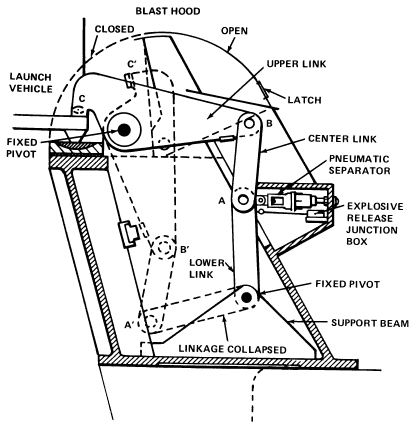
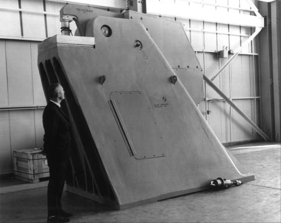
The first hold-down arm arrived at Huntsville on 31 October 1964, and testing began on 20 November. Due to a strike at a subcontractor’s plant, the second arm, scheduled for delivery on 19 November, came on the 28th. On 17 May 1965, engineers tested the ability of the first hold-down arm to sustain a vertical thrust of 725,747 kilograms. After the successful completion of all other tests on this arm on 25 May, workers installed and aligned an operational set of hold-down arms on launcher 3 at KSC. The other hold-down arms were ready by the end of the year.38
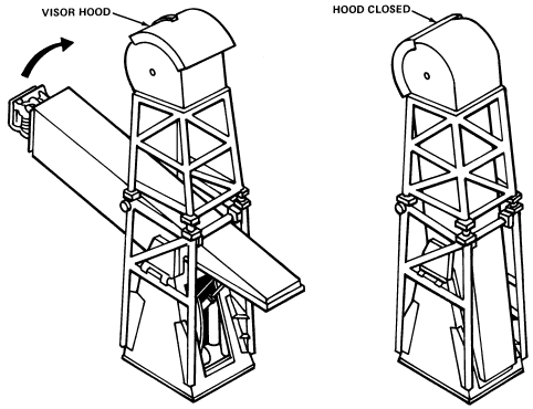
In addition to the four hold-down arms, three tail service masts would also stand on the base of each launcher. These provided support for electrical cables, propellant loading lines, hydraulic lines, and pneumatic lines servicing the first (S-IC) stage of the Saturn V. At liftoff a sequencer would hydraulically retract them, swinging them up and away from the Saturn V. A protective hood would fold over the umbilical connections on the end of each mast, protecting the connectors from the rocket engine’s exhaust. After constructing and testing a prototype of these devices, the American Machine & Foundry Company of York, Pennsylvania, built the tail service masts.39
Launch Pads
The launch pads at complex 39 were more than just raised, hardened areas for the launching of the Saturn V. There would be no permanently emplaced launch stands, umbilical towers, and service structures as previously associated with a complete launch complex. At LC-39 these structures would be mobile, and the pad had to be of sufficient strength to support their weight and that of the crawler-transporter. But the pad would have many other appurtenances common to its predecessors.
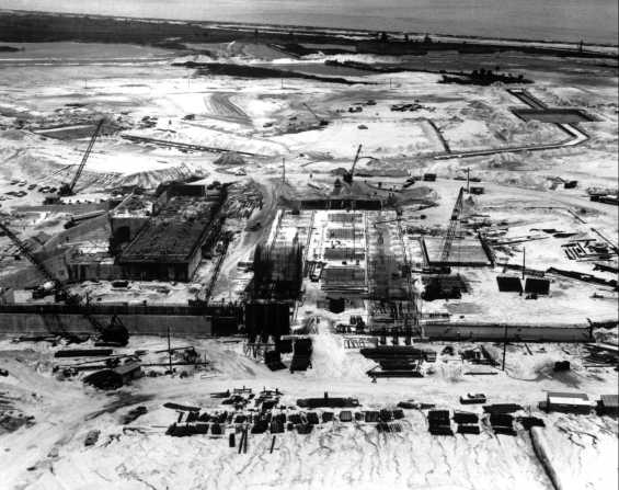
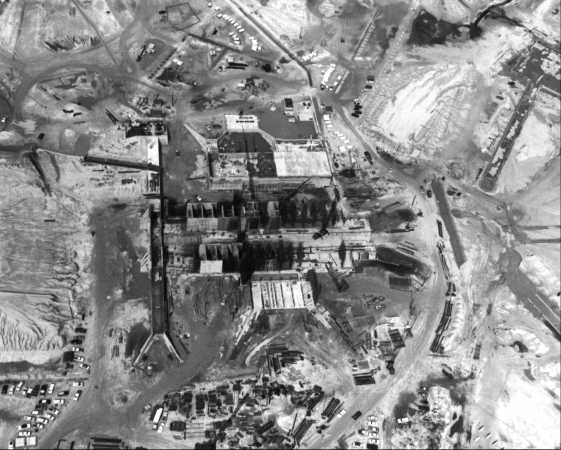
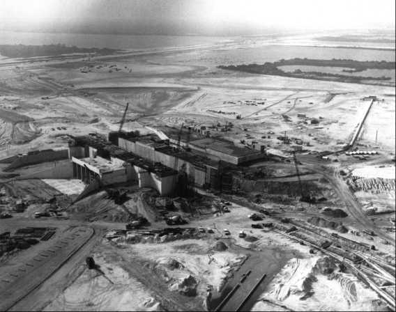

The site of launch pad A, approximately 0.7 square kilometers, was roughly octagonal. A contract with Blount-Sundt called for the construction of the pad proper, roads, camera mounts, utilities, and several other small facilities. The elevated launch pad, which would rise 12 meters above ground level, lay in a north-south direction. This orientation required the crawlerway to make a near right-angle turn before approaching the ramp sloping 5 degrees upward to the top of the pad. A flame trench, level with the surrounding area at its base, 18 meters wide and 137 meters long, would bisect the pad. On each side of this flame trench a cellular structure would support a thick surface, called a hardstand. The crawler-transporter would place the mobile launcher and the Apollo-Saturn vehicle on top of this reinforced slab.
The two-story pad terminal connection room and the single-story environmental control systems room would be within the western side of the pad. The former would house the electronic equipment that would connect communication and digital data link transmission lines from the launch control center to the mobile launcher when it was on the pad. The environmental control systems room would serve as the distribution point for air conditioning and water systems. The high-pressure-gas storage facility, to store and distribute nitrogen and helium gases piped from the converter-compressor facility, would lie beneath the top of the pad on the east side.
Should a hazardous condition arise that allowed safe egress from the spacecraft, the astronauts could cross over to the mobile launcher on a swing arm and then ride one of the high-speed elevators from the 104- meter level to level A, thirty stories down at 183 meters per minute. From there they would slide down an escape tube to a thickly padded rubber deceleration ramp. Steel doors, much like those of a bank vault, allowed access to a blast room, which could withstand an on-the-pad explosion of the entire space vehicle. Those inside could stay alive for at least 24 hours to allow rescue crews time to dig them out. The emergency egress system was part of the pad A contract.40
From Arming Tower to Mobile Service Structure
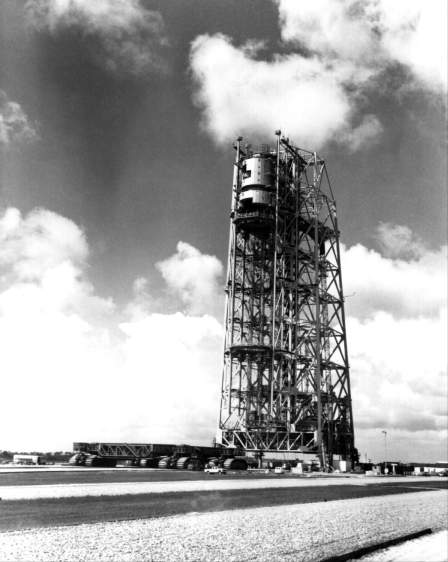
Originally conceived as a stationary arming tower, the mobile service structure went through many design changes before arriving at its final form. The structure, 125 meters high, nearly matched the mobile launcher in height as it stood on the opposite side of the Apollo-Saturn on the launch pad. The tall steel framework included five work platforms - the two lower ones vertically adjustable - that provided access to the space vehicle, and a base that contained several rooms. Shortly before launch, the crawler-transporter would move the mobile service structure along the crawlerway to a safe distance from the pad. The changing operational requirements during the construction of facilities made the mobile service structure one of the last essential facilities at launch complex 39 to get under way.
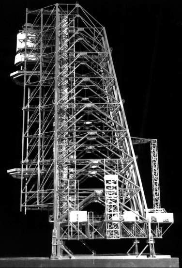
When the Rust Engineering Company of Birmingham undertook the design of the arming tower in February 1963, it faced a difficult task - designing a structure that would satisfy Apollo requirements but not exceed the load-carrying capability of the crawler. Initial meetings between NASA and Rust engineers concentrated on requirements for installing vehicle ordnance. Discussions on 21 March disclosed a major problem with the installation of linear-shaped charges - charges that would separate the stages during flight and, if necessary, destroy the vehicle. Their placement on the Apollo-Saturn required access from the arming tower at the interstage sections of the S-IC, S-II, and S-IVB, as well as at each stage that required a destruct package. As the tentative tower design with these features exceeded the load capability of the crawler’s front end, NASA engineers agreed to see if the shaped charges could be installed in the VAB. The tower would still serve to arm the various destruct charges and install the Saturn’s retro and ullage rockets. After reviewing the matter the following week, Gruene supported the use of the VAB; he also recommended a hazards study to confirm the safety of the proposed change. Meanwhile the Rust engineers dropped from their design the requirement to install shaped destruct charges.41
Wind loads were a second major concern for the tower’s designers. On 28 March representatives of the Marion Power Shovel Company, the Corps of Engineers, LOC, and Rust agreed to design for a maximum wind velocity of 100 kilometers per hour. When resting on its supports at the launch pad, however, the arming tower was to be able to sustain considerably higher winds. NASA officials cancelled the latter requirement two weeks later: in the event of a hurricane, the tower would be removed from the pad area.42
Rust Engineering completed the criteria for the mobile arming tower on 1 May and began the design work two days later. At a design review in September, the Corps of Engineers asked Rust for a thorough analysis of the tower’s weight and wind-load factors on the crawler. The review showed that the arming tower was overweight. During the next two months, numerous changes were made to bring the weight down to the crawler’s capability, but the efforts met with little success.43
On 3 December 1963 Debus asked the Corps to reexamine the arming tower. Within three weeks, the Corps submitted the results of several studies. In the first, Strobel and Rengved, consulting engineers, retained the basic Rust configuration but reduced the size of the work platforms and eliminated the air conditioning equipment. In contrast, Rust recommended reaching the weight limit by eliminating one of the five service platforms, one of the three elevators, and the air conditioning. While the Rust proposal got rid of more weight than the Strobel and Rengved study, it also reduced the operational flexibility of the tower. The Corps then asked the two firms for another study, this time a completely new design. Rust’s study employed fixed platforms, Strobel and Rengved’s movable platforms. Both resulted in overall weight reductions but no significant reduction of wind loads on the crawler.44
While the studies were in progress, a KSC decision rendered the work superfluous. At a Huntsville meeting on 10 December, KSC’s representative announced a new policy for the installation of ordnance at LC-39. Ullage rockets, retrorockets, the separation charges for the Apollo escape system, and other small ordnance items would be installed in the VAB. Detonators would be installed at the pad after the arming tower had been removed, by technicians using the mobile launcher’s swing arms for access. The arming tower; no longer required for ordnance installation, thereby became the mobile service structure.45
That change made Rust’s job much easier. Despite delays in receipt of spacecraft data from the Manned Spacecraft Center [see chapter 9-5], Rust completed the redesign work by July 1964. The combine of Morrison-Knudsen, Perini and Hardeman won a construction contract on 21 September in the amount of $11,587.000. Steel fabrication started at once, and actual construction got under way on 21 February 1965. Because of the late start, minor labor delays, and the late delivery of material, the framework of the mobile service structure had only reached the 13-meter level by mid-1965. From then on, however, work moved rapidly ahead. By the end of September, steel erection had reached the 68-meter level, and the workers topped out the structure at 122.5 meters on 19 November 1965, only four months late.46
Work on the crawlerway progressed steadily, and by the end of 1964 it was 83% complete. The converter-compressor facility was complete, and mechanics were installing equipment. The concrete paving, the supports for the high-pressure-gas lines, the foundation for the mobile service structure at its parking position - all were ready. Interior architectural, electrical, and mechanical work moved forward in the pad terminal connection room, while joint occupancy of the environmental control system room began on 28 December 1964.47
At pad A, activities moved ahead of schedule, with the completion of all major concrete work. As the middle of 1965 approached, the launch pad lacked only the paving of aprons and road, the placement of refractory brick, the digging of ditches, and the testing of components and systems.48
Lightning Protection for Apollo Launch Operations
KSC officials had been concerned about lightning strikes since the start of the Apollo program. The Cape Canaveral area averaged more than 70 thunderstorms per year, twice the national average. Although there had been little lightning damage to missiles during the 1950s, the height of the Saturn vehicle greatly increased the chances of a strike. Studies made in 1962 pointed up the hazard to LC-39. General Electric engineers predicted that the VAB would receive five lightning strikes per year, the mobile service structure and mobile launcher four strikes per year. The potential for lightning damage had prompted a Marshall-LOC meeting in August 1962. The group recommended contracting with General Electric’s High Voltage Laboratory for a lightning protection study and appointed LOC the technical supervisor. In February 1963, Petrone set up a committee on lightning protection, under Hayward D. Brewster, to review the GE proposals.49
The GE study served as the basis of the committee report submitted to Debus in July 1963, which concentrated on four problems, all during prelaunch operations: protection of the vehicle against a direct strike, the induced effects of a strike, mobile launcher grounding in transit, and corona. The placement of a lightning mast atop the mobile launcher was the straightforward solution to the first problem. Some authorities, however, did not think the traditional “cone of protection” applied to a structure as tall as the mobile launcher.* Electrical engineers also differed as to whether bonding and shielding on the mobile launcher would lower induced voltages to an acceptable level. Unless KSC could protect the launcher from both a direct strike and the secondary induced voltage, some other lightning diverter, such as balloons, would have to be used. GE module tests demonstrated that the cone-of-protection theory did apply to the mobile launcher and that practical measures would protect the vehicle and support equipment circuits from induced voltages. Besides a retractable mast for the launcher,** the committee recommended “general grounding, shielding, and bonding techniques . . . throughout the LC-39 area in order to keep the high voltage imposed by lightning strokes anywhere on the complex to a safe level.”50 An extensive underground counterpoise of rods and interconnecting conductors was eventually built into LC-39. Thousands of ground rods, driven deep enough to achieve a one-ohm resistance, tied together the crawlerway, service structure parking area, perimeter fence, and pad. Similar counterpoises protected cross-country cabling.51
GE engineers recommended certain precautionary measures when the mobile launcher was in transit. If a threat of lightning existed, personnel would stay inside the mobile launcher, or at least six meters from the crawler. Insulated ladders would be used for movement on or off the crawler. The committee proposed a backup warning system to alert personnel of approaching storms. The actual grounding of the crawler was simple - it would drag a chain along a conductor buried in the crawlerway.
A bluish electrical discharge, sometimes called St. Elmo’s fire, occurs frequently when storm clouds pass over tall structures. GE investigated the possibility of this phenomenon igniting a hydrogen explosion, but found that the corona would likely appear on the top outer edges of the mobile launcher and mobile service structure. This posed no threat, since the S-IVB lines ran 30 meters below the top of the launcher. The hydrogen lines to the Apollo service structure would shield the spacecraft connections during loading. The GE team rated the corona hazard a “negligible risk.”52
During the next three years, Brewster’s committee implemented the safety features on LC-39 while KSC’s Instrumentation Division set up a system to collect more data. A GE study of LC-34’s and LC-37’s needs led to a second set of committee proposals approved by Debus in November 1964. At a September 1965 meeting of the Lightning Protection Committee, R. H. Jones, an Instrumentation Division engineer, reported thirteen measured strikes during the previous year. One bolt had killed a construction worker on LC-39, pad B. Another strike on the Cape side had delayed Gemini II operations at LC-19 by several weeks (the lightning had damaged a number of electrical components in the spacecraft and supporting equipment). E. R. Uhlig of GE’s High Voltage Laboratory pointed out the correspondence between the measured incidents and GE’s earlier predictions.53
When Apollo launch operations began in 1966, KSC applied strict safety rules for lightning protection. All launch personnel evacuated the mobile launcher, mobile service structure, and space vehicle when lightning was detected within five miles of the pad. A half dozen lightning storms delayed operations but never for more than a few hours. KSC relaxed its provisions somewhat in 1970 as experience demonstrated the safety of the mobile launcher and service structure. Thereafter operations on the tall structures, excepting electrical work, continued in the face of an approaching storm.54
- In the early 1960s experts disagreed about the generation and incidence of lightning and about its behavior and effects. The cone-of-protection theory held that all strokes would terminate on a tall structure in preference to a shorter structure located within the conical volume whose apex was the height of the tallest structure and whose base radius was equal to the apex height. Evidence from lightning strikes on skyscrapers and church steeples indicated the theory applied to the top half of the cone; the disagreement concerned the protection provided to the lower half.
- The mast retracted so that the mobile launcher could get into the VAB.
Flame Deflectors
The last of the major facilities for launch complex 39 to reach the contract stage was the 635-metric-ton flame deflector. It would protect the lower section of the Saturn launch vehicle and the launch stand from high pressures and flame during ignition and liftoff. It would move on rails in the flame trench to a position beneath the Saturn V’s massive booster engines. The reflector, shaped like an inverted V, would send the flames down each side of the trench. It would be constructed of structural steel beams and trusses, supporting a steel skin. The skin was covered by 10 centimeters of ceramic material capable of withstanding the direct flame and pressure effects of the Saturn first stage engines. On 5 November 1965, Heyl and Patterson, Inc., signed a contract in the fixed amount of $1,465,075 for the manufacture, installation, and erection of three deflectors.55 Ultimately there would be a fourth, with one in use and another in reserve at each pad.
Without doubt, the many amazing structures under way on complex 39 - the world’s largest building, the crawler-transporters, the hold-down arms, the mobile launchers - constituted one of the most awesome building programs in the world. After the American Society of Civil Engineers considered engineering projects from every part of the country in 1966 - the Astrodome in Houston, the North California Flood Rehabilitation work, the Trans-Sierra Freeway from Sacramento to the Nevada line, and the hurricane barrier at New Bedford, Massachusetts, among others - it recognized launch complex 39 as the outstanding civil engineering achievement of the year.56
ENDNOTES
- D. D. Buchanan, memo for the record, 16 April 1962.X
- LOC, Procurement Plan, signed by Kurt Debus, Director, 11 Sept. 1962, p. 2.X
- DDJ, 1, 7 Nov. 1962; Debus to Brackett, 29 Nov. 1962; LOD, “Crawler/Transporter Proposal Conference Attendees, 17 December 1962” (in Buchanan file).X
- R. P. Young, Exec. Off., memo for record, 13 Mar. 1963, in NASA History Office; James E. Webb and Robert C. Seamans, Jr., “Statement of the NASA Administrator on Selection of a Contractor for the Crawler-Transporter,” 13 May 1963, ibid.; Congress and the Nation, 1945-1964 (Washington: Congressional Quarterly Service, 1965), p. 320.X
- "Briefing, Crawler-Transporter Procurement,” 5 Feb. 1963, copy in Fred Renaud’s private papers.X
- "Decision to Negotiate an Individual Contract under 10 USC 2394 (a) (11),” 5 Dec. 1963; “Determination and Findings for Method of Contracting, Cost-Plus-Incentive Fee... 7 Dec. 1962, both in NASA History Off.X
- W. Kraft, Admin. Asst., Marion Power Shovel Go., to Theodor A. Poppel, 11 Dec. 1963, pp. 1-4, in Fred Renaud’s private papers.X
- Ibid., pp. 5-6.X
- Renaud interview, 4 Apr. 1973.X
- Aviation Week 84 (20 June 1966): 78.X
- Gramer interview, 19 July 1973.X
- "Fire Alarm System for Crawler-Transporter,” 29 Jan. 1965, in Fred Renaud’s private papers.X
- Gorman to Petrone, 22 Mar. 1965, including a memo of 29 Feb. (sic) 1965, in Fred Renaud’s private papers.X
- "Fire Protection Survey and Recommendations,” attachment to letter of C. W. Conway to Ronald Worchester, 16 June 1965; copies in Fred Renaud’s private papers.X
- Spaceport News, 15 Feb. 1968, p. 6.X
- Unless otherwise cited, the descriptive information in this and the following paragraphs concerning the crawlerway and launch pad A facilities is based on the LC-39 Facilities Handbook, pp. 35-51.X
- Spaceport News, 19 Sept. 1963, p. 1; 17 Oct. 1963, p. 1; Tabulation of Corps of Engineers Contracts, Sept. 1968; “Summary Project Status Report,” 29 Nov. 1963, pp. III-2. IV-3; Technical Progress Report, Second Quarter CY 1965 (TR-194), 30 July 1965, p. 38.X
- Apollo/Saturn V MILA Facilities Descriptions, report K-V-011, p. 1-26.X
- Memo, Col. Bagnulo, 3 Feb. 1965.X
- Hahn interview.X
- Boylston interview.X
- Wm. Clearman, Prototype of Service Arm 6, 30 July 1963, on microfilm in Vehicle Servicing and Accessories Sec. of Design Engineering Off., KSC.X
- "Qualification Test for Cable Retract Sled for Saturn V and Pneumatic Console No. 2,” prepared by C. Dyer, Brown Engineering, in Design Engineering Files; photographs in Brad Downs’s Design Engineering Files, KSC. The authors are indebted to Mr. Downs for his help in this section.X
- "Weekly Notes,” Haworth, 5 Aug.; Clark, 6 Aug. 1964; Gramer interview, 19 Sept. 1972.X
- "Weekly Notes,” 19 Aug. 1964.X
- Technical Progress Report Third and Fourth Quarter CY 1964 (TR-159), 5 Mar. 1965, p. 61; “Saturn V Swing Arm Program Problem,” an analytical statement, unsigned and undated. This contract was NAS 10-1751.X
- Rowland interview; R. D. Rowland, Hayes International Corp., to Benson, 25 July 1972.X
- James W. Dalton and Willard Halcomb, Apollo-Saturn V Test and Systems Engineering Off., to Petrone, 28 Oct. 1964; “Saturn V Swing Arm Program Problem,” p. 1.X
- William L. Clearman, Jr., Chief, Apollo-Saturn V Test and Systems Engineering Off., to Chief, Launch Equipment Support Sec., Procurement Div., “Contract NAS10-1751, Proposed Changes to Incorporate Revised Drawing Lists,” 23 Nov. 1966.X
- James W. Dalton, Apollo-Saturn V Test and Systems Engineering Off., “Minutes of Meeting - Change Review Board - Service Army Contract with International - 17 Sept. 1964,” 22 Sept. 1964; Method of Handling Engineering Changes, Contracts NAS10-1751-NAS10-1847.X
- James W. Dalton to William T. Clearman, “Status of Hayes Service Arm Contract as Result of Sole Source Vendor Items,” 2 Dec. 1964.X
- "Saturn V Swing Arm Program Problem,” p. 2.X
- Kurt H. Debus to L. F. Jeffers, Hayes International Corp., Birmingham, AL, 5 Nov. 1965.X
- "Saturn V Swing Arm Program Problem,” p. 1 ; “Management Inquiry into the Procurement of Service Arms for Launch Complex 39,” pp. 42, 43, 62.X
- "Saturn V Swing Arm Program Problem,” p. 1; Gramer interview, 21 Sept. 1972.X
- Spaceport News, 28 Oct. 1965, p. 3.X
- Technical Progress Report Third and Fourth Quarter CY 1964 (TR-159), 5 Mar. 1965, p. 61; Procurement Div., “Status Summary of Active Contracts as of 31 Mar. 1964,” sec. II, p. 25.X
- Technical Progress Report Third Quarter CY 1965 (TR-250), 30 Sept. 1965, pp. 3-18.X
- Saturn V Launch Support Equipment General Criteria and Description (SP-4-37-D), rev. 15 Sept. 1964, Launch Support Equipment Engineering Div., pp. 2-62; Technical Progress Report First Quarter CY 1965, 26 Apr. 1965, p. 46; KSC Procurement Div., “Status Summary of Active Contracts as of 30 Sept. 1966,” sec. II, p. 6.X
- "Apollo Saturn V MILA Facilities Descriptions,” pp.2-81, 2-82; “Construction Progress Reports,” 1 July 1965, p. 4.X
- R. T. Cruden and J. R. Ellis, memo for record, “Ordnance Meeting, LC-39 Arming Tower,” 25 Mar. 1963; J. R. Ellis, memo for record, “Ordnance Requirements, Arming Tower LC-39,” 26 Mar. 1963; W. T. Clearman, Jr., and James H. Deese, “Meeting at Complex 34 Operations Support Building to Discuss Saturn-V Ordnance Installation Problem,” 27 Mar. 1963. The authors are indebted to Francis Jarrett for research on this subject, which is covered more fully in Jarrett and Lindemann, “History of the John F. Kennedy Space Center, NASA, to 1965,” typescript.X
- J. R. Ellis, memo for record, “Meeting and Discussions Concerning Arming Tower, LC-39,” 9 Apr. 1963; minutes of meeting, “Rust Contract BE-9002, LC-39 Arming Tower, Contract DA-08-123-ENG-(NASA-1752),” 15 Apr. 1963.X
- Off. of the Canaveral Dist. Engineer, “Report on Restudy of Arming Tower to Resolve Dead Load and Wind Load Problems,” 20 Dec. 1963, pp. 1-5.X
- Ibid.X
- Vehicle Design Integration Working Group, “Minutes of the Saturn V Common Ordnance Meeting,” Huntsville, AL, 10-11 Dec. 1963, pp. 1-4.X
- "Summary Project Status Report,” 17 Apr. 1964, p. lV-3; “Development Summary Schedule, Complex 39, 1963"; Technical Progress Report, Third and Fourth Quarter CY 1964, 5 Mar. 1965, pp. 45, 58; Tabulation of Corps of Engineers Contracts, Sept. 1968; Technical Progress Report, Second Quarter CY 1965, 30 July 1965, p. 38; Technical Progress Report, Third Quarter CY 1965 (TR-250), 30 Sept. 1965, pp. 3-18; LC-39 Facilities Handbook, p. 54.X
- Technical Progress Report, Third and Fourth Quarter CY 1964 (TR-159), 5 Mar. 1965. p. 45.X
- Technical Progress Report, First Quarter CY 1965 (TR-168), 26 Apr. 1965, p.33: Technical Progress Report, Second Quarter CY 1965 (TR-194), 30 July 1965, p. 34.X
- H. D. Brewster and E. G. Hughes, Lightning Protection for Saturn Launch Complex 39, report TR-4-28-2-D, 18 Oct. 1963.X
- Ibid., app. A.X
- Ibid., pp. 3-6 through 3-16 and app. A.X
- Ibid., pp. 2-3, 3-3, 3-4, A-1; A. R. Raffaelli, “Introduction to Lightning,” report LOC LT1R-2-DE-62-6, 14 Dec. 1962.X
- H. D. Brewster to Lightning Protection Committee, “Minutes of the Third Lightning Protection Committee Meeting, 29 Sept. 1965, at KSC,” 20 Oct. 1965, KSC Technical Documents Library.X
- KSC, “Weather Effects on Apollo/Saturn V Operations, Apollo 4 through Apollo 13,” report 630-44-001, 27 July 1970.X
- KSC release 11-66, 21 Jan. 1966.X
- Building Construction Magazine, Feb. 1966, p. 29.X