Launch Complex 34
The Director
The Missile Firing Laboratory’s director, Dr. Kurt Debus, had wasted no time in getting a launch pad ready for the new rocket. Early on the morning of 26 September 1958, four days after the Medaris-Johnson Agreement to launch four Saturn boosters, a small group of MFL members left Huntsville Airport for Patrick Air Force Base. They joined the Cape Canaveral members of the MFL team in Debus’s office for a discussion of ways and means of putting the proposed super-rocket into space.
After the Army had relocated its missile team from Fort Bliss to Huntsville in 1950, Wernher von Braun became Technical Director of the Ordnance Guided Missile Center. Debus, who had worked with von Braun at Peenemunde, was Assistant Technical Director. When von Braun established an Experimental Missile Firing Branch, Debus was placed in charge. The name was changed to Missile Firing Laboratory in January 1953, with Debus remaining at the helm. MFL maintained offices at Huntsville, although Debus spent much of his time at Cape Canaveral. During his early years at the Cape, Debus wrestled with a gamut of problems. One was a shortage of experienced people; a year after its formation, his team had only 19 members. The launch team for Redstone 1 in the summer of 1953 numbered 82, but only 37 were permanently assigned to the Missile Firing Laboratory. As the Redstone and Jupiter programs burgeoned, MFL grew also and by 1960, on the eve of its transfer from the Army to NASA, numbered 535 people. Thus, while the well-known “von Braun team” operated in Alabama, a less known and initially subsidiary “Debus team” was growing up at Cape Canaveral.1
Slowly the qualities of Dr. Debus became evident as he moved out of the shadow of the more charismatic von Braun. A doctor of philosophy in engineering from Darmstadt University, Debus had been headed for a professor’s chair when he was recruited into the Peenemunde group. Debus was a systematic man; he kept a daily journal and believed a well-ordered desk was a sign of an orderly mind. On his monthly inspections, he might help a subordinate clear his desk of nonessentials; or he would do it himself if the man was away at the time. He purged his own files regularly.
Totally committed to his work, Debus expected total commitment from those with him. Thus he would have less respect for a happy-go-lucky individual, no matter how well that man might do his job, than for one who shared his own seriousness of deportment. He set his goals and brooked no opposition to them. But he allowed his subordinates a choice of methods in reaching those goals. He relied more on his personal experience of a man’s capabilities than on records or written recommendations - a penchant he could not indulge in later years as the operation expanded. While not outgoing in manner, he had a deep concern for others. He showed the same reserved courtesy to the electrician who interrupted his busy day to replace a burned-out fluorescent tube as to the congressional leader who came to his office to discuss launch operations. While his team was small, he remembered birthdays with letters and cards. Straightforward in approach, he let his achievements speak for him - not always the most effective means of getting ahead. He was a man to get the job done. Now his job was to put a Saturn into space.
The proposed super-rocket dwarfed anything heretofore handled by the Army Ballistic Missile Agency (see table 1). The problems caused by the clustered engines were particularly significant. To guarantee proper ignition of all engines, The booster would have to be held on the launch pad for a few seconds. A complex mechanism to do this had to be developed. There was also a psychological factor, related to the Saturn’s great expense. With previous military missiles, launch equipment failures had been relatively inconsequential. Each program called for a number of tests; the MFL staff learned from mistakes. The millions of dollars tied up in each Saturn, however, meant that launch facility failures could not be tolerated. Finally there was the problem of time. With the first launch only two years away, there could be no serious delay in determination of criteria, in design, or in construction.2
TABLE 1. COMPARISON OF ROCKETS LAUNCHED BY MFL/LOD/LOC, 1953-1965
(Vehicle characteristics varied during rocket development; figures represent an approximate average,)
| Characteristics | Redstone | Jupiter | Saturn I (Block I) SA-1-SA-4 |
Saturn I (Block II) SA-5-SA-10 |
|---|---|---|---|---|
| Height (meters) | 21 | 18 | 50 | 58 |
| Diameter (Meters) | 1.75 | 2.63 | 6.40 | 6.40 |
| Propellant Weight (Kilograms) | 18,000 | 38,500 | 290,000 | 450,000 |
| Total Weight at Liftoff (Kilograms) | 28,000 | 50,000 | 430,000 | 515,750 |
| Total Thrust (Newtons) | 333,600 | 667,200 | 430,000 | 1st Stage 6,690,00 2d Stage 400,300 |
| RF Links | 2 | 4 | 8 | 13 |
| Telemetered Measurements | 116 | 215 | 560 | 1,180 |
| Pad Time | 15 | 25 | 61 | 103 |
Conversations with the Air Force
The purpose of the MFL staff meeting on 26 September 1958 was to determine the support requirements needed from the Air Force. A number of topics were discussed including safety zones, construction costs, fuel requirements, instrumentation, a service structure, and a launch site. The matter of a site, for what would eventually be launch complex 34, received further attention that Friday afternoon when Debus introduced the Saturn project to Maj. Gen. Donald N. Yates, Air Force Missile Test Center Commander. Debus suggested placing the new complex in the central part of the Cape near pad 26. That pad was presently in use for the Jupiter program, but would be phased out in 1960. Yates believed that construction near LC-26 would interfere with other contractors and pose safety problems. He suggested the use of areas near complex 20 (Titan), complex 11 (Atlas), or at the north end of the launch area, which had been tentatively reserved for large boosters.3
During the next two weeks an MFL facilities team made a preliminary survey of five possible sites. James Deese drew upon eight years of Cape experience in directing the survey. The team focused much of its attention on ground safety. The potential blast effect of an explosion on the pad established a ground safety zone and a minimum intraline distance. The safety zone, marking the danger area for exposed personnel, would be cleared of all persons 39 minutes prior to launch. The minimum intraline distance delimited the area within which a pad explosion would cause damage to adjacent pad structures or vehicles. Deese estimated that the fuel would have half the explosive force of TNT. With an estimated fuel load of 476 tons (equivalent to 238 tons of TNT), the three-stage Saturn would require a ground safety radius of 1,650 meters and intraline distance of 400 meters. The proposed firing azimuths (44 to 110 degrees) excluded sites that would result in overflying permanent launch facilities already constructed to the east.4
The Deese team recommended only one site, an area approximately 300 meters north of complex 20. By using the existing Titan 1 blockhouse (launch control center) at LC-20, costs and construction time would be minimized. The Air Force Missile Test Center objected to this location, contending that the Saturn pad should be at least 610 meters from other structures. This precluded joint use of the Titan blockhouse, because the data transmission equipment used in checkout of the Saturn would be adversely affected by voltage drops over a 610-meter circuit.* MFL arguments that the Air Force recommendation would increase facility costs by 30% and construction time by four months proved to no avail. In mid-January, after a six-week delay, the Advanced Research Projects Agency sited the Saturn complex 710 meters north of pad 20.5
- Some MFL officials believed the Air Force simply did not want to share blockhouse 20. The Air Force, however, consistently gave range safety a high priority. As General Yates recalled, the Air Force received numerous complaints from contractors because of concessions the Missile Test Center made to MFL.
Writing the Criteria Book
Criteria development for the Saturn complex proceeded more cordially. Close coordination was required between four groups: MFL, the Systems Support Equipment Laboratory of the Development Operations Division at Huntsville, the Jacksonville District Office of the Army Corps of Engineers, and an architect - engineering firm. Their goal was to collect and organize all the data necessary for satisfactory design and construction. The procedures used in developing Saturn launch criteria followed a pattern set in earlier programs. MFL and the Systems Support Equipment Laboratory prepared basic data on all launch facilities and equipment. The architect-engineer then formalized the data in a criteria book. The Army Corps of Engineers reviewed this document for cost, utility, and compliance with federal and Atlantic Missile Range codes. The launch criteria book provided a general description of facilities, proposed methods of construction, the placement of utilities and equipment, facility dimensions, distances between facilities, cost estimates, and preliminary drawings.6
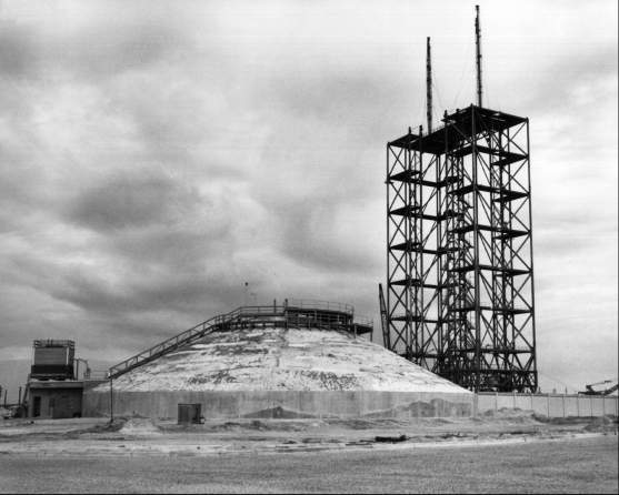
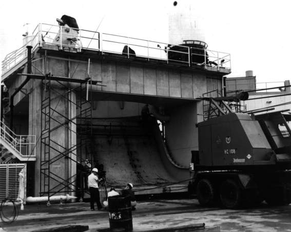
The blockhouse for LC-34 was patterned after the control center at complex 20. The reinforced concrete design permitted the planners to locate the structure 320 meters from the launch pedestal. A domed roof would be built up in three layers: an inner layer of reinforced concrete 1.5 meters thick; a middle layer of earth fill 2.1 to 4.2 meters in depth; and a 10-centimeter cover of shotcrete. The last, a concrete with a high cement content was pressure driven through a 15-centimeter tube onto a reinforced mesh screen. The 930 square meters of floor space provided room for 130 persons, with test and launch consoles, instrumentation racks, remote control fueling devices, and television and periscope equipment for the observation of activities on the launch pad. Blockhouse operations required substantial air conditioning for such equipment as computers, as well as for the people. Should a delay in firing occur after the rocket was fueled, the blockhouse could be buttoned up for 20 hours. Two tunnels provided escape routes in case an explosion sealed the door.7
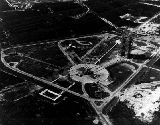
Two Cape veterans, R. P. Dodd and Deese, drew up preliminary criteria for the launch complex. Their plans called for a two-pad complex with only the northern pad (pad A) constructed initially. A raised concrete circle 130 meters in diameter would form the base of the pad. The central area’s slight depression facilitated replacement of refractory brick after a launch. Dodd included a water deluge system to reduce the intense heat and wash away spilled fuel, which would be channeled toward a perimeter trench. A skimming basin would prevent kerosene from entering the area’s drainage ditches. Beneath the pad, a series of rooms provided space for mechanical and electrical checkout and firing equipment such as terminal boards, instrumentation racks, electrical cables, and generators.
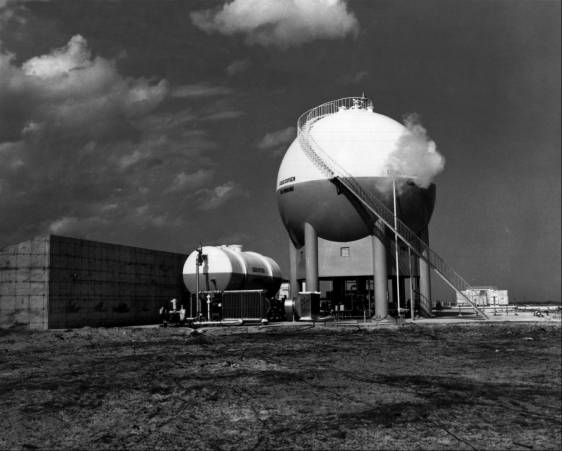
Three facilities along the south edge of the complex would service the Saturn’s propellant needs. In the southeast corner near the ocean stood tanks for RP-1, a grade of kerosene, to fuel the Saturn I booster (first stage). The liquid oxygen (LOX) tank in the middle of the southern boundary stored the oxidizer for all Saturn stages. This tank was insulated; in its liquid state, oxygen is cryogenic - super cold - with a boiling temperature of 90 kelvins (-183 degrees C). Dodd and Deese placed a high-pressure-gas facility in the southwest corner of the complex, near the blockhouse. The tanks in this storage area held two gases, nitrogen and helium, used in launch operations. Large amounts of nitrogen were used to purge and dehumidify the cryogenic lines that ran from the LOX tanks to the Saturn vehicle. The nitrogen also actuated LC-34’s pneumatic ground support equipment. On later launches, gaseous helium would be used to purge the hydrogen fuel lines to the Saturn upper stages. With an even lower temperature than liquid oxygen, liquid hydrogen boils at 20 kelvins (-253 degrees C). Since nitrogen would solidify in the presence of liquid hydrogen, helium was substituted. A few bottles of nitrogen and helium went aboard the launch vehicle to pressurize some of the subsystems.
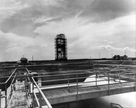
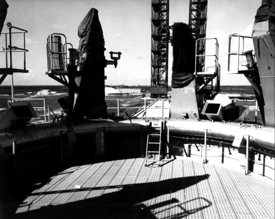
In the final plans, the flame deflector and its spare were parked north of the pedestal. The service structure pulled away on rails running from the pad to a parking area 185 meters west. The designers placed the umbilical tower on the northeast side of the launch pedestal. Eventually 70 meters high, it would carry fuel lines and other connections to the Saturn before liftoff. Two requirements governed the location of the umbilical tower and the service structure: the need for clear lines of sight from the erected launch vehicle to radar and telemetry stations in the industrial area 3 kilometers to the southwest, and an anticipated launch azimuth of 75 to 90 degrees.8
Problems in Design
At Huntsville the Systems Support Equipment Laboratory designed the ground support equipment, a term applied to components used in the preparation, testing, monitoring, and launching of a rocket. The interface, or fit, of the launch vehicle and the support equipment largely determined the design of the latter. Accordingly, work in the Systems Support Equipment Laboratory paralleled Saturn development and was very much a research and design effort. Five design problems, in particular, challenged the laboratory: the launch pedestal, the hold-down and support mechanisms, the deflector, the cryogenic transfer equipment, and the umbilical tower.
Initial launch pedestal plans called for a hexagonal structure of tubular steel. George Walter, the laboratory’s expert on structures, suggested a reinforced concrete design, which was eventually adopted. Walter’s pedestal, 13 meters square and 8 meters high, was supported by corner columns and opened on all four sides to allow use of a two- or four-way flame deflector. A torus ring of large water nozzles, designed by Edwin Davis, encircled the 8-meter-wide exhaust opening. During launch and for some seconds thereafter, the nozzles would spray water on the pedestal, across the exhaust opening, and down the opening’s walls, cooling the deflector and pedestal.9
Designing the eight vehicle support arms to be located on top of the pedestal proved a long and difficult task. Four of the arms, cantilevered at the Saturn’s outboard engines, would retract horizontally after ignition, providing clearance for the engine shrouds at liftoff. Should one of the engines fail during the first three seconds following ignition, these four arms could return to the support position. The possibility of damaging the rocket as it settled back on its supports complicated the design of the arms. The Systems Support team developed a nitrogen-fed pneumatic device that brought the support arms safely back under the launch vehicle within 0.16 second. The remaining four support arms were designed to hold the vehicle on the pad for three seconds after ignition so that blockhouse instruments could test engine thrust. Donald Buchanan’s design section considered more than 20 different proposals before selecting one suggested by Georg von Tiesenhausen, Deputy Chief of the Mechanical Branch. Von Tiesenhausen’s concept, modeled after an old German bottle top, had been planned for use in securing a Jupiter seaborne model.* The hold-down arms employed an over-center toggle device to achieve the necessary leverage and rapid release capability.10
The flame deflector design stirred debate within the laboratory: Should it have two or four sides? Should it be dry or wet (with cold water circulating through pipes beneath the metal shield)? The Huntsville engineers ruled out the four-sided deflector, previously used for Redstone and Jupiter missiles. The flame, spewing in all directions, would obstruct vision from the blockhouse and endanger equipment at the base of the umbilical tower. Both the size and cost of a wet deflector were unacceptable; one similar to those used on the test stands at Redstone Arsenal would cost ten times more than an uncooled deflector. Its size would increase the height of the launcher platform above ground, a dimension MFL wished to minimize. Despite doubts that a dry deflector could survive a single launch, a two-way uncooled deflector was selected.11
Fueling the Saturn promised to be another problem. The booster required 182,200 liters of liquid oxygen (LOX), six times the amount expended by the Jupiter missile. The LOX would evaporate at a rate of 163 liters every minute during fueling and up until launch; some provision for replenishing this loss was required. Explosive hazards dictated placement of the LOX facility a minimum of 200 meters from the launch vehicle. Orvil Sparkman, a Huntsville native who had been working on propellants since 1953, was responsible for designing the cryogenics equipment.
The main storage tank would be an insulated sphere with a diameter of 12.5 meters; it could hold 473,125 liters of liquid oxygen. A centrifugal pump would deliver the LOX through an uninsulated aluminum pipe to the filling mast on the launcher. This was the “fast fill” and operated at 9,460 liters per minute. With some of the LOX boiling off as its temperature rose during the filling process, a smaller (49,205-liter) tank would send additional LOX through a vacuum-jacketed line to replace the boil-off, thus keeping the vehicle tanks full. Since the launch team wanted to automate LC-34 fueling, remote controls were designed for the launch control center. Early plans called for a differential pressure sensing system in the rocket’s LOX and RP-1 tanks to control propellant flow (much as a washing machine controls flow by measuring the difference in pressure between the top and bottom of the tank). At Debus’s request, the system was later replaced by an electrical capacitance gauge. The LOX tank’s fuel level sensor also actuated a pneumatic valve on the replenishing line.12
- In November 1955, Secretary of Defense Charles E. Wilson directed the Navy to adopt the Jupiter as a shipborne IRBM. Navy leaders, unenthusiastic about seagoing liquid-fueled rockets, subsequently were able to replace the Jupiter with the solid-propellant Polaris missile.
A Service Structure for Saturn
MFL’s Mechanical Branch, meanwhile, considered the assembly, transport, and service of the launch vehicle. The March 1959 criteria book called for checkout of the Saturn stages in hangar D in the Cape’s industrial area, transfer to the pad, and erection and mating of the stages on the pad. The plan required extensive modifications to hangar D, as the booster’s size necessitated an increase in hook height from 8 to 13 meters. This additional space could be provided by cutting the roof structure from its columns, jacking the entire roof up as one assembly, and building up the columns.13
Some of the Development Operations Division’s plans for a Saturn service facility, drawn in terms of a 25-meter booster and limited funds, seem primitive in contrast with the eventual structure. One early study proposed to eliminate service platforms by designing the upper stages with sufficient work space inside the rocket. Another short-lived scheme lowered platforms down over the launch vehicle, attaching them to the rocket’s outer surface at the required working levels. Workers would ride elevator stands up to the work platforms. In a November 1958 memorandum, Albert Zeiler scoffed at the notion of men servicing a rocket from a little platform, high above the ground. He said it would be “practically impossible” to perform assembly and checkout tasks, especially in bad weather. In addition, the rocket would be exposed to rain and high winds; in the event of the latter, it would have to be secured by guy wires.14
He recommended instead a large stand with lifting equipment to assemble and erect the booster and upper stages. Service platforms to support personnel and equipment, elevators, and weather protection would be incorporated in the stand.
MFL awarded the criteria studies for the launch complex and service structure to the Miami firm of Maurice H. Connell and Associates. The Miami architects, veterans of the Redstone program, completed both studies by mid-March 1959. At a conference later that month, Saturn engineers agreed to complete design work by 1 August 1959. The conference set a 1 July 1960 target date for construction of the complex, excepting the blockhouse and service structure.15
Connell and Associates had completed the criteria studies and moved into the design phase when MFL decided on major revisions in the assembly and service concepts. Prior to the criteria review, IDECO, a Dressler Industries division, had approached MFL with a proposal for a tubular steel service structure. It was designed in the shape of an inverted U, open at both ends. IDECO’s design offered several advantages: greater accessibility to the booster, a minimum hook height of 13 meters, and more flexible service platforms (the platforms telescoped in and out of the main frame design, were vertically adjustable, and could match up with various booster or upper stage diameters).16
An additional attraction of the IDECO proposal stemmed from a new MFL proposal to assemble and check out stages of the launch vehicle in a building 180 meters from the launch pedestal. The facilities people at the Cape had never really liked the idea of modifying hangar D; many thought the raised roof would collapse in a hurricane. In the new plan the staging building shared a bridge crane with the IDECO service structure. Rails at the ceiling level of the staging building matched up with the bridge crane rails at the 13-meter level in the service structure. A cutout portion in the center front of the staging building roof provided space for the bridge crane roof. The dual use of the bridge crane allowed the transfer of the stages from the staging building to the launch pedestal in one operation.17
General Medaris was impressed with the IDECO proposal and ordered an extension of the service structure study. At a 13 April meeting, MFL directed Connell representatives to prepare a new design incorporating 14 function capabilities of the IDECO proposal. The Miami firm satisfied this requirement in ten days. The design called for a structure of girders and platforms shaped like an inverted U 95 meters high. The service structure was 40 meters wide, including the 17-meter open space where the structure extended over the launch pedestal. A bridge crane supported 40- and 60-ton hoists at a 75-meter hook height. Each hook had a forward reach of 9 meters and a lateral reach of 6 meters. Seven fixed platforms were housed within the tower legs, each providing 73 square meters of working area. Each half of the six enclosed retractable platforms had a capacity of 12 persons and 272 kilograms of equipment. The platforms were vertically adjustable from the 25-meter to the 68-meter level. Three elevators provided a 227-kilogram lift.18
Construction bids followed in June. Since assembly and service methods were still not firm, the contract called for additional design work. Kaiser Steel Corporation’s $3.9 million bid, $400,000 less than an IDECO proposal, won the contract. Kaiser formally began work on 14 August 1959, but construction did not start until the following summer.19
Brick and mortar work on the new complex proceeded satisfactorily, slowed little if at all by the still meager Army appropriations and the prospects of major administrative changes taking form in Washington. In early June 1959 the Western Contracting Company began hydraulic-fill operations at the pad. A proprietary process, vibroflotation, was used to compact the fill, The Vibroflot machine consolidated the marshy soil by simultaneous vibration and saturation; the machine vibrated the sand with ten tons of centrifugal force as it pumped in more water than the surrounding soil could absorb. The sand formed a dense mass, the excess water floating fine particles to the surface. Workmen shoveled in backfill (roughly 10% of the total volume compacted) to increase the density. Vibroflotation on LC-34 required 5,350 cubic meters of fresh sand to provide compact soil 8.5 meters deep. In late November, the Henry C. Beck Construction firm started work on the pad facilities. Three hundred and twenty meters to the southeast, the blockhouse was taking shape.20
A Money Transfusion
In the meantime, Debus received good news. With the Saturn’s metamorphosis from Army orphan into NASA prima donna, cost estimates at the launch facility could be revised upward to what were considered more realistic levels (see table 2). Limited Army financing had constrained the Development Operations Division to view the Saturn program as a minimum operation to demonstrate the feasibility of the clustered booster, and funding for its Cape Canaveral launch facility during the first nine months was piecemeal and unrealistic. As a later MFL study noted: “Prior to this date [31 July 1959] no budget submissions could be considered an estimate of requirements, merely a series of proposals on how to apply initial inadequate funding with the promise of additional operating funds to come."21 Rough estimates in September 1958 placed the cost of the launch complex at $4.5 million. The original project request, made on 9 March 1959, called for a total expenditure of $8.7 million. The price of the service structure alone had increased from $400,000 to $3,000,000. By 31 July 1959, revised estimates had increased the figure for MFL expenditures to $13.1 million, with an additional $8 million requested for ground support equipment. One year later MFL officials would be justifying a $38 million price tag for LC- 34. Their explanation would offer a number of reasons: underestimates, inflation, organizational changes, vehicle design alterations, and the Saturn program’s changing guidelines and objectives.22
Besides the rising costs of LC-34, MFL faced the need for a backup Saturn launch complex. While the Silverstein Committee report was pending in late 1959, MFL began its own investigation of hydrogen-filled upper stages. A committee, headed by Charles Hall, examined equivalent TNT forces and concluded that an explosion would render LC-34 useless for a year. MFL reassessed its Saturn launch capability in light of that report. The LC-34 staging building, tentatively located near the pad, was moved back to the industrial area and the service structure was fitted with blow-out panels around the base. In January 1960, Debus notified Eberhard Rees, Deputy Director at Huntsville, of the Hall Committee findings and strongly recommended a second Saturn complex. Construction of LC-34’s second pad would not do since the 730 meters separating the LC-34B site from LC-20 was too short for safety, with the new Saturn configuration. The Development Operations Division gave its approval and MFL was soon planning for what would become launch complex 37.23
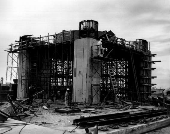
With the transfusion of new money, construction of LC-34 proceeded apace. Reminiscent of Florida’s Seminole Indian Wars of the 1830s, the first structure to take form was the blockhouse (launch control center). The dangers had changed and so, too, the design of the blockhouse. The interior diameter of the igloo-shaped building at LC-34 was 24.4 meters, its maximum height 7.9 meters. Two stories provided space for control instrumentation, measuring racks, and firing consoles. Construction took 13 months; the blockhouse was ready for occupancy in July 1960.
Table 2. Launch Complex 34 Cost Estimates
| 9 March 1959 | 31 July 1959 | August 1960 | |
|---|---|---|---|
| Blockhouse | 1.3 | 1.1 | 1.1 |
| Service structure | 3.0 | 4.6 | 5.1 |
| Launch pad and area development | 3.6 | 5.4 | 5.4 |
| Capital equipment (high-pressure-gas systems, instrumentation) | 0.3 | 2.0 | 2.5 |
| Ground support equipment | 8.0 | 23.1 | |
| Operations support building | .9 | ||
| Industrial facilities | .5 | ||
| Totals | 8.7 | 21.1 | 38.1 |
The Ground Support Equipment
At Marshall Space Flight Center the development of ground support equipment proceeded under a new office. With the reorganization of ABMA, on the takeover by NASA in March 1960, the Systems Support Equipment Laboratory disappeared. Most of the laboratory’s personnel joined LOD as members of Theodor Poppel’s Launch Facilities and Support Equipment Office (LFSEO). Poppel’s experience with ground support equipment dated back to World War II. A native of Westphalia, Poppel had begun work at Peenemunde in 1940, following graduation from an engineering school in Frankenhausen. He had been among the first Germans to enter the United States in 1945. The deputy to Poppel, Lester Owens, like many American members of the von Braun team, was Alabama-born and Auburn-trained. Five of the six suboffices worked in Huntsville; the other line unit, R. P. Dodd’s Launch Facilities Design Group, was based at the Cape.24
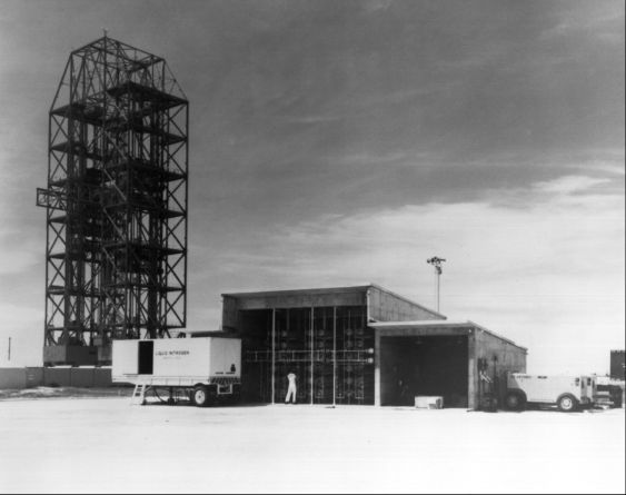
By May 1960, LFSEO leaders felt sufficiently confident about the development of ground support equipment to discuss responsibilities for installing equipment at LC-34. A conference on the 17th set beneficial occupancy dates (the dates on which each facility within the complex would become available to MSFC and its contractors for installation of collateral equipment). MSFC plans called for a rudimentary high-pressure-gas (nitrogen and helium) facility. Two flatbed trailers, each with a 3,785-liter storage tank, pump, vaporizer, and associated equipment, would bring liquid nitrogen to the pad. After being routed through a vaporizer and warmed to 294 kelvins (21 degrees C), the gaseous nitrogen would be stored under high pressure in a cluster of bottles protected by a concrete vault. Two booster compressors located in the storage area would pressurize the helium. Since the introduction of upper stages after the third launch would increase high-pressure-gas requirements, Chester Wasileski’s Propellants Service Design Group was planning a central compressor-converter for LC-37. The basic LC-34 arrangement, however, would be ready by 1 August 1960.
Discussion moved next to RP-1 facilities. LFSEO planned to test the integrated fuel storage and transfer system at Huntsville before 10 August. During the fall, the General Steel Tank Company would install the two 113,550-liter storage tanks at the pad. Hayes Aircraft personnel would then clean, install, assemble, and pressure-test the entire transfer system from tank to fuel mast. The two 3,785-liter-per-minute pumps were standard equipment and posed no problems. The propellant operations and status panel required additional testing at Huntsville, but would be ready for blockhouse installation in the fall. Wasileski thought the entire system could be operational by 1 February 1961.
Wasileski envisioned a similar schedule for LOX facilities: completion of testing at Huntsville on 10 August; installation of storage and replenishing tanks by Chicago Bridge Company between September 1960 and 15 January 1961; cleaning, assembling, and installing the transfer system (the pipes that carried LOX from the tanks to the Saturn) by Hayes before 15 January 1961; and operational status as of 1 February 1961. During the installation, the Chicago Bridge Company would conduct a flow test between the storage tank and replenishing tank to qualify the vaporizer design.
Work on the cable masts was proceeding satisfactorily. The Saturn booster required a 21-meter aluminum boom to service the instrument compartment with pneumatic pressure, electrical power, and coolants. LFSEO expected to deliver the long mast 1 March 1961. Shorter cable masts, mounted on the launcher support arms, would provide pneumatic and electrical connections to the tail section of the booster. The electrical connections powered and monitored the propulsion system, while the pneumatic lines purged and pressurized the fuel systems. The conference set 1 February 1961 as the installation date for launcher support arms, hold-down arms, and short cable masts.25
Development of the flame deflectors took Poppel’s office about six months longer than expected. LFSEO had begun testing angles of impingement in early 1960 to establish the flow pattern for the Saturn’s exhaust. If the deflector was set at the wrong angle, a detached shock wave would form, choke the exhaust flow, and raise the heat and pressure on the launch vehicle beyond tolerable limits. Donald Buchanan’s Launcher System and Umbilical Tower Design Section experimented with several angles before contracting with the Hayes Corporation of Birmingham to construct two 80 degree deflectors. Delivery was set for November 1960, During subsequent tests in August 1960, Buchanan and Edwin Davis determined that a 60 degree deflector (30 degree angle of impingement) would further reduce the backflow. Although the 80 degree deflector still met launch vehicle requirements, rocket designers prevailed upon von Braun to modify the Hayes contract. The Birmingham firm shipped the first deflector to the Cape in April 1961. Due to its size, 6 × 8 × 13 meters, and weight, 99 tons, the deflector was shipped in seven sections.26
The change in the deflector design was not a unique event. The office frequently altered its designs to fit requirements of other MSFC groups; few concessions were made to LFSEO. For one example, the support arms could have been simplified by strengthening the booster frame. This LFSEO recommendation was rejected because it meant adding 1,100 kilograms to the launch vehicle weight. Eventually, the weight increased several times that amount, but for other reasons. MSFC officials, fearful of a rocket collision, restricted the size of the umbilical tower. An LFSEO engineer, believing the final design of the tower base was unsatisfactory, surreptitiously increased its dimensions. Speculation about German-American friction at Huntsville was largely unfounded, but disagreements between vehicle designers and ground support engineers were common.
By mid-1960, costs of the two Saturn launch facilities were burgeoning. A July Saturn Project Office memorandum noted that “rising costs, the influence of the committee on Saturn blast potential [Charles J. Hall Committee], and the full impact of [the Saturn] C-2 on the VHF-37 complex... indicated that approximately 44 millions were required in lieu of the available 31 millions [for FY 1961]."27 The Launch Operations Directorate established priorities to complete the essential portions of LC-34 and LC-37 while the remaining facilities awaited adequate funding: first, prepare LC-34 for the three Saturn booster shots without hydrogen capability or umbilical tower; second, prepare LC-37 as a backup pad for the second launch; third, complete LC-37 for launch of a two- or three-stage Saturn C-1 or C-2; fourth, complete LC-34 for Saturn C-1 configuration.* Construction of LC-34’s umbilical tower began in September 1960 but stopped at the 8.2-meter level; the long cable mast would provide umbilical connections for the booster launches.28
- In July 1960, the Saturn launch schedule called for the first three booster shots to carry dummy upper stages. This was eventually changed to four booster shots (the block I series) and six two-stage launches (block II series). The block I series ran from 27 Oct. 1961 to 28 Mar. 1963.
Labor Difficulties
Construction on several of LC-34’s most prominent features including the service structure, launch pedestal, and umbilical tower was just getting under way when a serious labor dispute broke out at the Cape. On 5 August 1960, members of the electricians’ union (International Brotherhood of Electrical Workers) informed a Corps of Engineers representative that, “It’s too hot and ABMA is making it hotter. . . We’re going fishing."29 The Launch Operations Directorate had generated the heat earlier that morning when some of its personnel unloaded a dozen firing consoles at the launch control center. The incident touched off four months of conflict between LOD and labor unions at the Cape, and eventually received the attention of Congress and the Secretary of Labor.
Involved were jurisdictional issues between unions, as well as the role of labor unions in research and development work. During the late 1950s, the building trades unions had achieved jurisdiction over a large share of the construction of ground support equipment for missiles. They feared loss of such jobs to the aircraft industry union. LOD officials believed that the building trades unions had won a number of concessions at the Cape because the Air Force normally yielded to labor demands. While the urgency of military programs made the Air Force position understandable, Debus refused to take the same course.* LOD articulated its philosophy in a 6 September presentation to General Davis, Air Force Missile Test Center Commander:
All ground equipment including measuring, launch controls, plumbing, instrumentation which are directly connected to the missile are a very integral part of the missile system. In the early phase of any program, the missile constitutes a flying laboratory for the purpose of gathering data and testing feasibility on design concepts, operational techniques. . . Thus the ground equipment is just as important to the success of the mission as is the actual flight of the missile. . . and must come under the direct control, from installation to final use, of the LOD missile people. All our firings will be R&D in nature, not operational prototypes.30
General Davis was impressed with the LOD arguments, but not so the unions. When LOD personnel returned to the launch control center on 10 October to install more panels, 47 electricians walked out again. Ten days earlier, 27 ironworkers had left work on the service structure complaining of excessive supervision; on 4 October, 17 carpenters stopped work in a jurisdictional dispute with electricians over the installation of static ground lines.31
These walkouts were brief and contractors lost only 800 man-days from August to November. Then on 14 November LOD resumed its activities at LC-34, with civil service personnel installing cables and consoles. When the electricians struck again, LOD initiated injunction proceedings. The other trade unions retaliated with a mass walkout at the Cape. By Thanksgiving 650 union members were on strike. With the problem attracting national attention, Secretary of Labor James P. Mitchell intervened. His appointment of a fact-finding committee placated the unions and work resumed 28 November. The committee’s findings, released after the New Year, included recommendations that LOD improve its communications with the unions and that both sides re-examine the controversial interface points (between rocket and ground support equipment). While the basic issue remained and work stoppages continued, relations never again reached the low ebb of November 1960.32
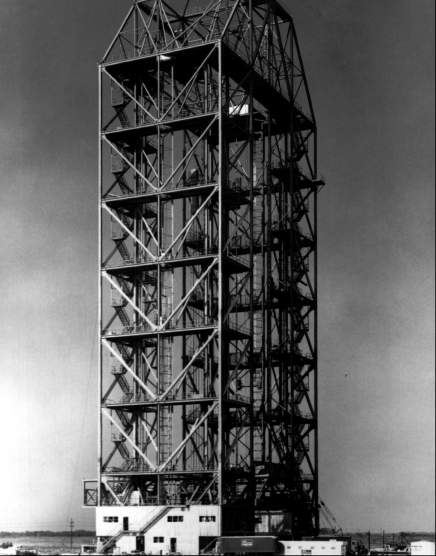
Work moved ahead rapidly on LC-34’s major structures in early 1961. By February the inverted U shape of the service structure’s rigid box truss frame was clearly recognizable. At the pad, four reinforced concrete columns, 7 meters high and more than 2 meters thick, stood at the corners of the 13-meter-square launch pedestal. Nearby rose the steel frame of the abbreviated umbilical tower. The walls of the 7 × 7 × 8-meter base would incorporate blowout panels to reduce structural damage from a pad explosion.
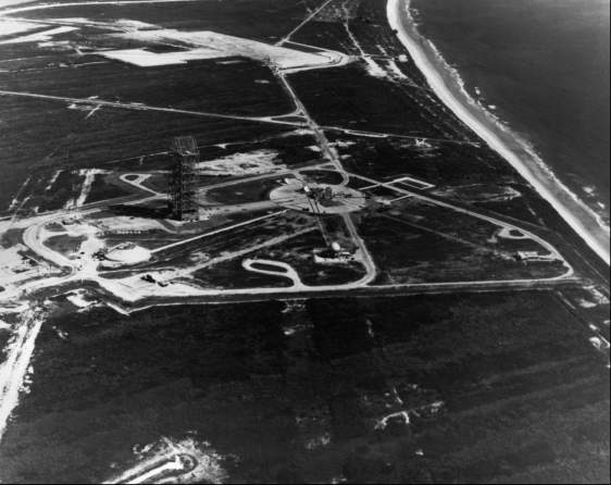
At its formal dedication 5 June 1961, LC-34 represented the largest launch facility in the free world. Although complexes 37 and 39 would soon overshadow it, LC-34 was destined to play an important and tragic role in the Apollo history. Its inaugural would come in four months with the first Saturn I launch as the United States tried to recover lost ground in the space race.
- Gen. Donald Yates contends that Air Force policy was a better approach to labor relations, Non-union contractors did work at the Cape, but the Air Force never placed a non union contractor on the same job with a union contractor. Furthermore, Yates felt that LOD leaders tended to challenge union labor with their new rules.
ENDNOTES
- Chief, MFL, to Chief, Ops. Off., Guided Missile Development Div. (GMDD), “Manning Charts,” 5 Jan. 1953; Chief, MFL, to Dep. Chief, GMDD, “Official List of Operations Personnel for Missile #1"; Launch Operations Directorate (hereafter cited as LOD), “Special Report on Support Operations at the AMR by LOD,” 21 Dec. 1960, part 5.X
- ABMA, Juno V Development, p. 47; Georg von Tiesenhausen, “Saturn Ground Support and Operations,” Astronautics 5 (Dec. 1960): 30.X
- Debus to C.O., Atlantic Missile Range (hereafter cited as AMR), “Juno V Program,” 1 Oct. 1958; Robert F. Heiser, Technical Asst., Off. of the Dir., MFL, memo for record, “Juno V,” 26 Sept. 1958.X
- Deese to Debus, priority TWX, “Feasibility Study and/or Criteria for a Launch Site at AMR for a Clustered First Stage of Juno V Project,” 8 Oct. 1958; Koelle, ed., Handbook of Astronautical Engineering, pp. 28-1 to 28-10; MFL, Juno V (Saturn) Heavy Missile Launch Facility, 1st Phase Request, 2nd Phase Estimate, by R. P. Dodd and J. H. Deese, 14 Feb. 1959, pp. 2-3.X
- Deese to Debus, “Feasibility Study for a Launch Site"; Warren G. Hunter, ARP A Coordinator, SSEL, memo, “Meeting at MFL, CCMTA on Juno V Launch Complex,” 10 Nov. 1958; Pan American Aviation, “Juno V Program Siting Study,” 24 Oct. 1958, pp.1-3.X
- Glen W. Stover, Chief, Facilities Br., AMR, Army Field Off., memo for record, Criteria Contract, Juno V Facilities, 10 Nov. 1958; Maurice H. Connell and Assoc., Heavy Missile Launch Facility Criteria (Miami, FL, 15 Mar. 1959).X
- ABMA, Juno V Development, p. 55; LOD, “Complex 34 Safety Plan for SA-1 Launch,” 24 Oct. 1961, p. 2; Porcher interview.X
- MFL, Juno V (Saturn) Facility; Connell and Assoc., Launch Facility Criteria; Sparkman interview, 13 June 1974. For detailed descriptions of the Saturn C-1 Launch Complex with its ground support equipment, see Marshall Space Flight Center (hereafter cited as MSFC), Saturn SA-1 Vehicle Data Book, report MTP-M-S&M-E-61-3 (Huntsville. AL. 26 June 1961), pp. 133-65, and MSFC, Project Saturn C-1, C-2 Comparison. report M-MS-G-113-60 (Huntsville, AL, 16 Nov. 1960), pp. 33-47, 123-290.X
- Davis interview; Walter interview, 21 Sept. 1973.X
- Von Tiesenhausen interview, 20 July 1973; Buchanan interview, 22 Sept. 1972.X
- Davis interview; Koelle, ed., Handbook of Astronautical Engineering, p. 28-44.X
- MSFC, C-1, C-2 Comparison, pp. 167-83; Wasileski interview, 14 Dec. 1972.X
- Zeiler interview, 24 Aug. 1972; Connell and Assoc., Launch Facility Criteria, p. 2-9.X
- Zeiler, Chief of Mechanical Br., MFL, to Debus, “Servicing Equipment for Juno V on Launch Site,” 24 Nov. 1958.X
- Connell and Assoc., Heavy Missile Service Structure Criteria; Army Engineer Dist., Jacksonville Corps of Engineers, “Minutes of Conference on Review of Criteria for Saturn Facilities,” 7 Apr. 1959.X
- Robert E. Linstrom, DOD Saturn Project Engineer, memo for record, “Summary of Fifth Saturn Meeting,” 1 Apr. 1959; Debus’s Daily Journal (hereafter cited as DDJ). 13 Apr. 1959, KSC Director’s Office; Debus, memo for record, “Meeting on Saturn Service Structure,” 9 Apr. 1959.X
- Debus, memo for record, “Meeting on Saturn Service Structure,” 9 Apr. 1959; Connell and Assoc., Alternate “I” Heavy Missile Service Structure, 24 Apr. 1959, R. P. Dodd’s personal papers.X
- MSFC, SA-1 Data Book, pp. 131-33.X
- DDJ, 13 Apr., 22 June, 11 July 1959; “ Corps of Engineers Contract Tabulations for LC-34, LC-37, and MILA Facilities,” p. 3.X
- ” Vibroflotation,” Vibroflotation Foundation Co., Div. of Litton Industries, Pittsburgh. PA, undated pamphlet.X
- J. P. Claybourne to Robert Heiser, priority TWX, “Saturn Launch Facility Costs,” 7 Sept. 1960.X
- J. P. Claybourne, memo for record, “Cost of Saturn Launch Facilities and Ground Support Equipment,” 13 Sept. 1960.X
- C. C. Parker, Technical Program Dir., memo for record, “Saturn Launch Facilities at AMR,” 3 Dec. 1959; Connell and Assoc., Siting Study and Recommendation, Saturn Staging Building and Service Structure, Complex 34 AFMTC, Jan. 1960, pp. 2-3; MSFC, C-1, C-2 Comparison, p. 35; Debus to Rees, “Additional Saturn Launch Complex,” 29 Jan. 1960; ABMA, A Committee Study of Blast Potentials at the Saturn Launch Site, by Charles J. Hall, report DHM-TM-9-60 (Redstone Arsenal, AL, Feb. 1960).X
- MSFC, C-1, C-2 Comparison, pp. 100-102; Poppel interview, 12 Feb. 1973.X
- MSFC, C-1, C-2 Comparison, pp. 123-63, 206-20, 244-67; Poppel, memo, “Launch Equipment Installation at Complex 34, AMR,” 27 May 1960; Sparkman interview. 15 Dec. 1972; Wasileski interview, 14 Dec. 1972.X
- Davis interview, 2 Feb. 1972; Poppel, memo for record, “Contract NAS8-46 Extension,” 29 Dec. 1960; Poppel to Petrone, “Documentation of Major Facility and/or GSE Changes for Project Saturn,” 23 Feb. 1961, p. 5.X
- C. C. Parker, Chief, Ops. Off., MSFC, “Saturn FY-61 LOD Budget,” 29 July 1960, encl.3.X
- Debus, memo, “Priority of Effort on Saturn Launch Facilities,” 8 July 1960.X
- R. P. Dodd to C. C. Parker, 8 Aug. 1960.X
- Debus to Wernher von Braun, “Labor Situation,” 21 Sept. 1960.X
- George V. Hanna, “Chronology of Work Stoppages and Related Events, KSC/NASA and AFETR through July 1965,” KSC historical report (KSC, FL, Oct. 1965), pp. 26-27.X
- Ibid., pp. 30-35; DDJ, 15 and 28 Nov., 5 and 22 Dec. 1960.X