Launching the First Saturn I Booster
The Magnitude of the Task
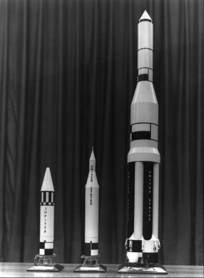
Just as launch complex 34 dwarfed its predecessors, Saturn checkout represented a new magnitude in launch operations. The Saturn C-1 stood three times higher, required six times more fuel, and produced ten times more thrust than the Jupiter. Its size, moreover, was only a part of the challenge to the Launch Operations Directorate (LOD) at Cape Canaveral. The costs and complexity had also increased markedly. Because of the costs (eventually $775 million for the Saturn I program’s research and development alone), there would be fewer test flights. This meant the engineers at Marshall Space Flight Center (MSFC) had to have more test data per flight - such measurements as the temperature of the flame shield, the pressure in combustion chambers, the rocket’s angular velocity in pitch and roll. Whereas two telemetry links (radio transmitter-receiver systems) sending 116 measurements had been adequate for Redstone testing, the first Saturn booster employed eight telemetry links to report 505 measurements. The rocket’s overall complexity necessitated a longer checkout: Saturn C-1 launch preparations averaged 9 weeks, almost three times longer than for a Jupiter missile.1
Ultimately the new procedures were to work a major change in the human role on the launch pad. Until the Saturn, the Debus team had been on a first-name basis with the rockets. LOD members who were not crawling around inside the Jupiter worked within a few yards of the pad. The Saturn brought little change initially; checkout for the first Saturn C-1 remained largely a manual operation. In the block house, a console operator with a test manual threw a switch connected to a rocket component and checked the results on a meter or strip chart. Automation on the first Saturn booster was rudimentary, limited to relay logic during the last minutes of countdown. It increased as the Saturn grew more complicated. The addition of a live second stage to the Saturn C-1 and the appearance of the much larger Saturn V dictated greater reliance on machines and computers. By the mid-1960s the Saturn checkout was well on the way to automation. Chapter 16 will address this subject in detail.
NASA had firmed up the Saturn C-1 program in late 1959 by adopting the Silverstein Committee’s proposals (pages 13-14). Marshall Space Flight Center would start with the clustered booster (S-1) and dummy upper stages. A second block of missions would add a hydrogen-fueled second stage, and a third block would add a third stage to the stack. The Program Office listed the SA-10 launch, set for April 1964, as the Saturn C-1’s debut as an operationally ready vehicle. Plans beyond the ten-vehicle research and development (R&D) schedule were indefinite. A 1960 NASA Long Range Program called for 50 Saturn C-1 and C-2 launches between 1965 and 1970. Twenty of these flights would launch Apollo spacecraft reentry tests, earth orbital missions, and circumlunar shots.2
These plans were altered in January 1961 when Wernher von Braun proposed to eliminate the third stage; a two-stage Saturn C-1 would meet the needs of the early Apollo missions. Following NASA Headquarters formal approval of von Braun’s recommendation, the Saturn Office in Huntsville rearranged the ten-vehicle R&D program. Block I, beginning that fall, would consist of four S-1 stage tests from LC-34 (mission numbers SA-1 through SA-4). Block II, the next six launches (SA-5 through SA-10), would add the second stage from the LC-37 launch pad, and from an upgraded LC-34.3
The Saturn C-1 test flights were to prove the design of the launch vehicle. The block I launches in particular would test the eight-engine propulsion system, the clustered tank structure, the first-stage control system’s ability to cope with sloshing and nonrigid-body dynamics, and the compatibility of the vehicle and launch facility. During the block I series, Marshall engineers proposed a systematic buildup of tests to prepare the way for two-stage flights. Broadly stated, LOD’s responsibilities were fourfold: assuring that transportation had not affected vehicle components, mating stages and ground equipment to verify the compatibility of the different stages, launching the rocket, and analyzing the performance of all vehicle systems immediately after launch to detect flight failures. Although the mission was referred to as “launch vehicle test and checkout,” less than half of LOD’s scheduled activities involved test performance. The balance of the total launch preparation effort included activities more properly described as assembly, installation, preparation for test, and evaluation of records.4
The Leadership
Entries in the LOD Director’s daily journal during 1961 indicate that Debus kept a close eye on SA-1 operations. Other problems, however, occupied his time: a new launch facility for Saturn V - eventually the moonport for the moon rocket; Centaur facility development; and Mercury-Redstone, Pershing, and Ranger launches. On account of these duties, Debus did not deal with the details of the SA-1 checkout. That burden fell on his operations office chiefs, their deputies, and the veteran test engineers.
Dr. Hans Gruene headed the Electrical Engineering Guidance and Control office. A native of Braunschweig, Germany, he had earned his engineering degree at the technical university in his home town. Gruene had joined the Peenemunde operation in 1943 and emigrated to Fort Bliss after the war. Since 1951 he had served as the electrical networks chief for the launch team. Small in stature and unassuming, Gruene enjoyed great respect from his associates. Gruene’s deputy, Robert Moser, had joined the von Braun team as an Army enlisted man in 1953, three years out of Vanderbilt University. He had reverted to civilian status in 1955, but stayed on in Huntsville as Gruene’s right-hand man. Moser’s launch countdowns resembled an orchestral performance and earned him high praise as test conductor for Explorer 1 and Alan Shepard’s Mercury-Redstone flight, Gruene’s office supervised the performance of all equipment affecting rocket guidance and control. This required a wire-by-wire knowledge of the electrical systems, both on board the vehicle and at the launch site. Gruene’s men also evaluated preflight telemetry records relating to guidance, stabilization, control, and electrical networks of the vehicle.
Albert Zeiler’s Mechanical, Structural, and Propulsion Office handled missile receipt and transfer, stage erection, and assembly. The team tested pressures, located leaks, and made necessary replacements, repairs, or modifications. One of the branch’s sections was responsible for fueling the rocket, another for the firing. After the launch, the branch evaluated flight data to check on mechanical functions and make corrections for future flights. The Austrian-born Zeiler had served at Peenemunde throughout World War II, testing and launching V-2s. Following duty at White Sands, he had moved to Huntsville and worked with MFL. Robert Gorman, deputy in the Mechanical Office, had begun his engineering career in NACA’s wind tunnels at Langley Field. A ready ear for subordinates’ ideas contributed to his success. His calm manner balanced Zeiler’s excitable nature, and the two provided the office with effective leadership.
Quiet and intense, Karl Sendler, chief of the Measuring and Tracking Office, seemed aloof to strangers, but to colleagues showed a warmth that sparked loyalty. He was Vienna-trained and reflected the traditions of the old Hapsburg capital in his manner and attire. At Peenemunde, Sendler had tracked the V-2s fired northward along the Baltic experimental range. He, too, had worked at White Sands before moving to Huntsville in 1950. His deputy, Grady Williams, had graduated from Auburn in 1949 and joined the von Braun team three years later. Associates considered him one of the friendliest members of the team. Like Sendler, Williams had a penchant for order. The two gave the Measuring and Tracking Office a reputation for being immaculate. During checkout, Sendler’s systems engineers tested and calibrated the Saturn’s measuring instruments - pressure gauges, thermometers, accelerometers, and the telemetry that relayed the measurements back to earth. At launch his office collected the flight data. Supporting ground radars tracked the flight for deviations in direction and range, which would reveal problems in the guidance and propulsion systems. Along with the other offices, Sendler’s group prepared designs and established criteria for launch facilities. The unit’s work brought frequent contact with other agencies investigating telemetry, high-frequency signals, and the measuring and tracking of launch vehicle flights. The branch’s previous efforts had contributed to the development of three specialized tracking systems: DOVAP, “Beat-Beat,” and UDOP.* 5
The work of the three LOD operations offices involved close liaison with other Marshall divisions. Thus, Hans Gruene and his engineers spent more than half of 1960-1961 in Huntsville with the MSFC Guidance and Control Division. In turn, a dozen Guidance and Control engineers took part in the SA-1 checkout at the Cape. The launch team still considered itself an extension of Marshall. As one veteran recalled, “In the 1950s we looked at equipment when it came down here as not trusting a single thing in it. We were going to check everything from one end to the other."6 Consequently, LOD’s checkout was precise and exhaustive, “a laboratory type check on the pad."7 Basic operating procedures were established and followed closely.
Debus detailed some of these procedures in a letter to NASA Headquarters shortly after the first Saturn launch. LOD employed a test sequence that proceeded from components, through subsystems and systems, to overall tests. “If the preceding less complex tests are eliminated, as is tried frequently to shorten overall test schedules, any failure of one single component in an overall systems test necessitates activation of all other components whether critical to running time or not."8 Debus insisted that his engineers conduct at least one systems test in its entirety to ensure a total working package. Other rules, established from long experience, included: calibrating sensors at the latest possible time, removing all connecting circuitry and components in a system when the cause for random irregularities could not be established, and disturbing a minimum of electrical and pneumatic connections after the final overall test. Some procedures concerned LOD’s relations with other Marshall divisions. One provided for a speedy MSFC ruling on launch vehicle and ground support equipment modifications at the pad; another assured the availability of current Huntsville drawings.
The technical checkout of the various Saturn systems fell to LOD’s test engineers. Debus considered these engineers “the backbone of LOD test activities"; they carried “full responsibility for preparing a launch vehicle to the point of launch readiness [and] merited equal status with... engineers in design, development, and assembly operations. While an error made in the design or development phase could be detected by a test engineer, a mistake by an LOD systems engineer would inevitably lead to mission failure."9
Conceding that launch site tests were part of a continuous program to assure reliability and quality, Debus stressed the test engineer’s need for autonomy. “Since the systems engineer carries the full responsibility for the flight-readiness of his assigned system, this responsibility should not be attenuated by assigning a separate inspection or quality assurance team to check on the systems engineer for compliance to test procedures and test performance.” Although limited manpower ruled out a two-shift operation at the Cape, Debus opposed it on principle: “A systems engineer had to be kept informed continuously of the status of his assigned system and all occurrences during the test period."10 When problems arose, the launch team resorted to overtime. The work day during the SA-1 checkout varied from 8 to 16 hours.
- DOVAP (doppler velocity and position) was a velocity-measuring system that used a ground transmitter, a transponder on the launch vehicle, and a number of ground receivers. The change of frequency between the signal transmitted from the ground and that later received on the ground, called the doppler shift, could be converted to the velocity of the rocket. Integrating the velocity with time provided distance, which applied to the known departure point indicated the rocket’s position. The “Beat-Beat” system detected the deviation of a missile from a predetermined flight path. It derived its name from the use of two receivers that compared, or beat, two frequencies against each other. The system consisted of a pair of DOVAP receiver stations placed symmetrically about the flight path. When the missile deviated to the left or right, one receiver would detect an increasing frequency, the other a decreasing frequency. See W. R. McMurran, ed., “The Evolution of Electronic Tracking, Optical, Telemetry, and Command Systems at the Kennedy Space Center,” 17 Apr. 1973, mimeographed paper. “Beat-Beat” could be used equally well with UDOP or telemetry signals. UDOP (ultra-high-frequency DOVAP), operating at 440 megahertz, offered certain advantages over DOVAP, including higher resolution and less loss of accuracy from ionospheric refraction.
The Test Catalog for SA-1
LOD began preparing for the first Saturn launch in mid-March of 1961 when Debus directed the Scheduling and Test Procedures Committee to review launch procedures. The Director did not want to “automatically transfer into the Saturn, things that may have been important in past operations.”11 The committee - composed of the operations office deputies Gorman, Moser, and Williams - agreed that Saturn required basic changes in launch procedures. For example, LOD personnel had conducted a detailed identification of component serial numbers on previous rockets. Since a serial inspection of Saturn components would require many man-hours, the committee proposed to rely on MSFC’s detailed list instead. LOD would update the Marshall list when components were changed. The committee eliminated some redundant systems checkouts and recommended less component testing. During the Saturn C-1 launches, the emphasis would shift gradually from component testing to integrated systems testing. As the checkout for SA-1 was revised, other MSFC personnel undertook to coordinate all Saturn testing.12
The test catalog that emerged in May 1961 indicated the magnitude of the Saturn C-1 program. The catalog included 233 system tests, 102 of which were prepared by LOD. The tests were grouped in seven categories: electrical networks, measuring, telemetry, radio frequency and tracking, guidance and control systems, mechanical systems, and vehicle systems. The last category included overall tests, simulated flight tests, cooling systems tests, propellant loading tests, static firing, and fuel tank pressurization. Most of the tests ran from four to eight hours; a few required days. An example of LOD’s contribution was 6-LOD-26, the fuel and LOX systems full-pressure tests: 6 indicated the category, mechanical systems; LOD, the responsible division; and 26 identified the particular test among 42 in that category. The test objectives were to “accomplish a pressure test of both propellant tanks to full working pressure, performed and monitored from the Blockhouse to determine if any major structural defects have occurred due to transporting, handling, erecting, etc. Pressure drop-off time, and pressure switch cycles will be recorded for system leakage analysis at full working pressures.”13
While operations personnel were determining test requirements, construction at the launch complex progressed toward the 5 June 1961 dedication, when the Corps of Engineers would formally transfer LC-34 to NASA. LOD personnel began outfitting the service structure in early May. The propellants team used “live” fuel to run a “wet test” of the fuel system on the 19th, No serious leaks appeared in the LOX and RP-1 transfer lines, and the pumps worked satisfactorily. At the dedication ceremony the long cable mast and two short cable masts were the only major items missing, Redesign had slowed their development, but shipment from Huntsville was expected in mid-June.14
A new ground support requirement, however, threatened to delay the October launch date. On 11 May launch vehicle designers notified Maj. Rocco Petrone’s Heavy Vehicle Systems Office that the high-pressure gas system would have to be modified. Model tests indicated that LOX sloshing in the Saturn tanks caused condensation of the gaseous nitrogen used for pressurizing the fuel, and this lowered the pressure to marginal limits. The solution was to pressurize the LOX tanks with helium. Petrone took immediate steps to procure a helium facility through sole-source procedures - an emergency government purchase without competitive bidding. He transferred LC-37 funds to cover the expense and secured eight steelworkers, skilled in working on high-pressure tubes. Debus told von Braun the following day that the change to helium might hold up the launch. The Marshall director mentioned NASA Headquarters fear that a delay would have political repercussions, but assured Debus that Huntsville understood the problem. Modifications progressed rapidly, easing Debus’s mind, and the helium facility was ready by mid- September.15
Up in Huntsville, the Fabrication and Assembly Engineering Division had fallen behind on its booster assembly schedule. Debus reluctantly agreed to have the work completed at the Cape. Albert Zeiler detailed a list of unfinished items in a letter to Debus on 14 July. Zeiler expressed particular concern about the scheduling problems posed by these requirements:
| 3 | — | Install hula hoops [rings that retained the heat shield] and coat uncoated portion on eight engines. |
This would require 30 hours of unobstructed work in the tail section during the last 10 days before launch.
| 10 | — | Heat shield beams have to be coated, estimated time three days for application and up to ten days in addition where no work can be performed around the tail section because the coating discharges, during the curing time, burnable fumes. |
Zeiler considered this a safety, as well as a scheduling, problem, but noted that the curing time could possibly be shortened.
| 11 | — | Four curtains for outboard engines will be prefitted, then coated, and then shipped. |
The installation would require one day and should be done as late as possible to avoid any damage.16
Robert Moser was responsible for fitting the Fabrication Division’s activities into the Saturn checkout. As SA-1 test conductor, he coordinated launch operations and ensured that proper procedures were used for the 102 formal tests. Moser’s operations schedule, prepared in early August, included:
| 15 | Aug | — | Unloading barge and transporting S-1 stage to pad 34. |
| 17 | -21 | — | Erection of stages. |
| 15 | Sept. | — | Removing service structure for RE tests with the range. |
| 20 | -25 | — | Overall systems tests. |
| 2 | Oct. | — | LOX loading test, |
| 9 | — | Simulated flight test. | |
| 12 | — | Launch day. |
Moser’s schedule also listed much component testing and instrument calibration during the first half of the schedule; system and vehicle tests predominated in the second half. 17
The Saturn Goes Sailing
Two years earlier Marshall Flight Center officials had decided to transport the Saturn booster (SA-1’s only live stage) from Huntsville to Cape Canaveral by water. In April 1961, Test Division personnel loaded a waterballasted tank, the approximate size and weight of the booster, and a dummy upper stage aboard the barge Palaemon. The barge, resembling a Quonset hut on a raft, made the first leg of its trial trip in five days, descending the Tennessee, Ohio, and Mississippi Rivers to New Orleans. There, a seagoing tug replaced the river tug. The Palaemon crossed the Gulf of Mexico to the Florida Keys, sailed through the straits, and up the Atlantic coast via the Intracoastal Waterway. The LOD team on the Saturn dock, located at the south end of the Cape industrial area, witnessed a strange sight when the simulated booster emerged from the Palaemon’s hatch. The big spoked rings, 4.3 meters across, on each end of the 25 × 2. 1-meter tank, looked like the wheels and axle of a gigantic vehicle. The simulation served its purpose, proving that both the Palaemon and the Cape’s secondary roadways could carry the load.18
The Palaemon was undergoing modifications back at Huntsville in early June when the lock at Wheeler Dam, Tennessee, collapsed, stranding the barge upriver. Test Division and LOD personnel moved quickly to secure a reserve barge from the Navy’s mothballed fleet at Green Cove Springs, Florida. Although there was not enough time to construct a cover for the second barge, the Avondale Shipyards at Harvey, Louisiana, made emergency modifications. Concurrently, the Tennessee Valley Authority enlisted the Corps of Engineers to build a bypass road and dock at Wheeler Dam. The Navy had identified its drab barge by a number, YFNB33. NASA rechristened the vessel Compromise, in hopes it would prove a workable one.19
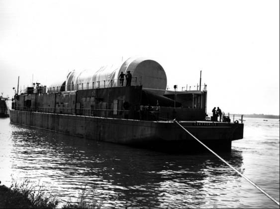
The booster was ready for shipment in early August, following static firing and two months’ further testing at Redstone Arsenal. To protect the booster during its voyage, the Test Division installed humidity and pressure regulating equipment within the LOX and RP-1 systems. Protective covers were placed on each end of the booster, as well as on the dummy upper stage and payload. After the assembled booster, with its support cradles, connecting trusses, and assembly rings, was jacked onto two axle-and-wheel units, an M-26 Army tank retriever towed the load to Redstone’s dock. Marshall engineers had provided for the Tennessee River’s three-meter fluctuation at the arsenal by building special ballasting characteristics into the Palaemon.20
The portage at Wheeler Dam, the reloading on the Compromise, and the journey to New Orleans went smoothly. Out in the Gulf of Mexico, however, the ten-man crew had rough sailing. Test Director Karl L. Heimburg attributed the handling problems to the Compromise’s insufficient ballast. Negotiating the Intracoastal Waterway proved even more difficult, and the Compromise went aground four times. Heimburg blamed this on unreliable channel depths due to the shifting of the loose, sandy bottom. Crosswinds were an additional hazard; besides threatening to blow the barge around, the wind caused several near-accidents at bridges. (The Compromise was to collide with a bridge on the return trip, causing minor damage.) Despite Heimburg’s frustrations, the SA-1 arrived unscathed at the Cape’s Saturn dock on the 15th.21
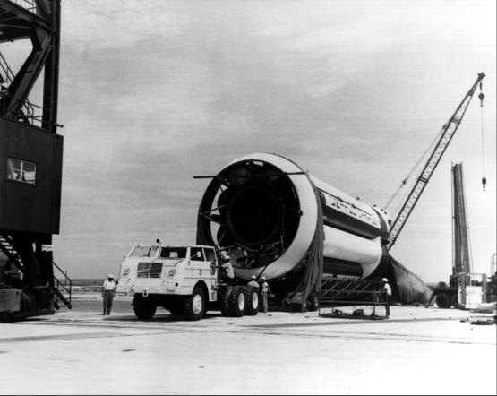
Unloading the booster was relatively easy in the almost tideless Banana River. Henry Crunk’s vehicle-handling unit towed the S-1 transporter across the Cape at a majestic 6.5 kilometers per hour. Although the operation required little physical exertion, the ten-man team perspired freely on the treeless Cape. At pad 34 ocean breezes made the heat and glare more tolerable. Most visitors, associating Florida’s beaches with leisure, would have found the mixed sounds of service structure cranes and pounding surf incongruous. The novelty for LOD veterans lay in the huge Saturn booster, which had at last arrived at its action station.22
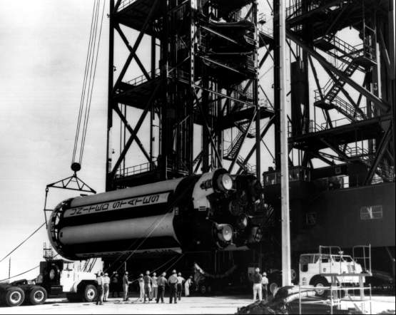
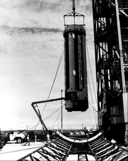
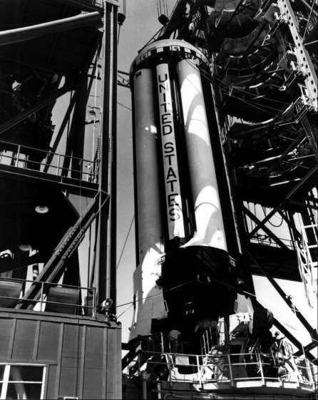
The booster or S-1 stage was erected on Sunday, 20 August. Crunk’s unit had practiced maneuvering a dummy tank on the pad, but this was the first mating of the booster to the launch pedestal. With the service structure in place over the pedestal, an M-26 driver positioned the transporter parallel to the service structure base. The crew connected crane hooks to pickup points on the booster, a 60-ton hook to the forward sling and a 40-ton hook to the thrust frame sling. The crane operator raised the S-1 stage vertically, brought it into the service structure, and lowered it onto four preleveled support arms. Removal of the transportation assembly rings proved the most time-consuming aspect of an uneventful operation. Early the following week, Crunk’s unit hauled the dummy stages and payload from hangar D, where they had undergone inspection. The handling unit mated the dummy stages and the nose cone on the 23rd. Cables and cable masts were installed, the four retractable support arms positioned, and network power applied on the 25th. Concurrently the Fabrication Division installed exhaust duct brackets, access doors, and the radio frequency shield.23
Beginning the Checkout
Andrew Pickett’s Vehicle and Missile Systems Group (part of Zeiler’s Mechanical Office) spent the next month installing the accessories of SA-1*
and conducting a series of launch vehicle tests. In some, the purpose was to make sure that various components responded correctly to pressure stimuli. Others checked for leaks caused by the barge trip and the subsequent erection of the S-1 stage. The first week the group performed pressure switch functional tests, verifying the pickup and dropout pressures for several hundred switches. The Saturn’s 48 nitrogen bottles, which pressurized the RP-1 fuel tanks during flight, were then tested at one-half the operating pressure.During the second week, the unit checked out the pressurizing and venting capability of the LOX tanks. Air pressure was applied to a switch in the tanks’ electrical system. The switch, when functioning properly, would terminate pressurization at a certain level. If excessive pressure built up, a second switch would vent the hypothetical gaseous oxygen. LOX and RP-1 system leak checks followed; in both tests the team pressurized the tanks to about one-half the operating pressure, looking for seal leaks.
Concurrently Pickett’s group conducted a series of engine tests. A nitrogen purge of the LOX dome, located at the top of the H-1 engine, served several purposes. A low-level purge, begun prior to propellant loading and continued until shortly before engine ignition, exceeded atmospheric pressure to prevent contaminants from entering the thrust chamber nozzle and flowing up to the injector plate and LOX dome. This also prevented moisture from condensing in the area. If a launch was cancelled, a full-flow nitrogen purge would quickly expel all LOX from the dome to avoid a possible explosion. Similar purges of the liquid-propellant gas generator, LOX injector manifold, and the fuel-injector manifold of the thrust chamber prevented the entry of unwanted substances.
The full-tank pressurization test on 6 September ended the first phase of mechanical checkout. Allowing for the possibility of an explosion while bringing the launch vehicle to full pressure, LOD officials cleared the pad for the Wednesday morning test. The two-hour exercise went smoothly, and that afternoon engineers were back at the launch vehicle for further operations.24
Calibration of the measuring devices that were to report more than 500 flight measurements was a daily operation. Sensing devices such as transducers, potentiometers, thermocouples, and strain gauges measured pressures, propellant flows, temperatures, and vibrations. A signal from one of these sensors, measured in millivolts, was routed to a signal conditioner which amplified the reading until it could be read on a scale of 0.5 volts. The calibration of these signal conditioners, popularly referred to as black boxes, was a major concern of Reuben Wilkinson’s Measuring Group (a unit of Sendler’s Measuring and Tracking Office). The team sometimes stimulated a sensing device by tapping on a portion of the rocket to cause vibrations or by placing a hot soldering iron near a thermocouple. More often they simulated a signal with an electrical input through an “interrupt box” located between the sensor and the signal conditioner. While calibrating the black boxes, the launch team bypassed the telemetry system. The amplified signal went from the signal conditioner through a series of remote-controlled relays, and then over wires to a measuring station in the base of the service structure. The calibrating equipment in the station normally performed a five-step sequence, checking the reading of each instrument at 0, 25%, 50%, 75%, and 100% of maximum value. After the tests were completed, Wilkinson’s team reconnected the measuring and telemetry systems for readings over the radio frequency (RF) links.**
The Measuring Group removed faulty instruments from the launch vehicle for further checks at calibration stands or in an instrument-calibration laboratory. The team was also responsible for the blockhouse measuring-station. Here LOD received 100 ground measurements on the rocket and ground support equipment, as well as telemetry data.25
Another of Sendler’s units, Daniel McMath’s telemetry team, checked out the booster’s eight RF links. Seven of the links used the XO-4B package, a proved system from Jupiter flights. The XO-4B was a PAM- FM-FM (pulse amplitude modulated-frequency modulated-frequency modulated) system with 15 channels of continuous data and 54 multiplexed channels.***
The Guidance and Control Division in Huntsville had developed the eighth link to ensure sufficient data channels for the Saturn C-1. The central feature in the new XO-6B was a 216-channel electronic commutating system.**** Sub-multiplexers sequentially sampled the same measurements for each of the eight engines. Sub-multiplex 1 might sample “temperature LOX pump bearing” while sub-multiplex 2 sampled “pressure at fuel pump inlet.” The main transistorized multiplexer, in turn, sequentially sampled each of the 27 sub-multiplexers. The multiplexer’s output was fed to a 70-kilohertz wide-band subcarrier. This frequency permitted the use of a commercially available oscillator that accurately carried the 3600-pulse-per second wave train and utilized existing demodulation equipment. The result was that 216 separate Saturn measurements traveled on one radio frequency.26
McMath’s Telemetry Group first tuned the two sets of antennas located at the forward end (top) of the S-1 stage. The six-man team next performed transmitter and power amplifier checks. A third operation, alignment of the subcarrier channels, involved tuning each subcarrier oscillator to its center frequency and band edges. The test also ensured that signal output from the oscillators was of correct amplitude. Midway into the second week the team began verifying telemetry wiring. Data was fed into each line at a break between the measuring and telemetry systems. If range operations permitted, the team conducted an “open loop test,” with the RF transmitter radiating the telemetry signal to receivers in the blockhouse and hangar D. But if radiating RE signals would interfere with any other activity in the area, the team operated “closed loop” with the signal going from the telemetry link over wire to the telemetry ground stations. After all eight links were checked out, the team reconnected the measuring and telemetry systems for subsequent tests of the launch vehicle.27
During the first month of checkout, Jim White’s Tracking Group worked on the tracking systems for the SA- 1: cameras, UDOP and UDOP Beat-Beat, S-band radar, C-band radar, Azusa, Beat-Beat MKII Telemetry, and Telemetry ELSSE.# The two radar systems were controlled by the Air Force. The S-band provided position data by tracking the Saturn beacon. The C-band was a backup, should the Saturn beacon fail. LOD had eight UDOP stations in the Cape area, each connected by RE data links to a central recording station in hangar D. The Beat-Beat MKII Telemetry employed two baselines: one set of antennas located south of LC-34 determined whether the rocket made its proper turn out to sea; the other set, southwest of LC-34, ascertained flight path deviations downrange. The UDOP Beat-Beat system would fly on SA-1 as an experimental package.28
White’s team employed a test transmitter to check out the UDOP stations. The test team simulated launch vehicle movement by varying the transmitted frequency. A drop in frequency simulated velocity away from the receiving station; conversely, a frequency increase represented rocket movement toward the receiver. These response tests checked the data-link equipment as well as the eight UDOP receiving sets. Preparation of the Beat-Beat systems included “walking the antenna,” a basic test, but one which pointed up the importance of the tracking unit’s work.##
First, antenna connections were broken at one end of the baseline. Then a team member, equipped with a hand antenna and field telephone, walked a certain distance to set up a new baseline. Launch vehicle signals received at the new baseline indicated a theoretical rocket deviation from the previous flight path (read at the old baseline), the degree and direction of the deviation depending on the man’s new location. By correlating the deviation and the new baseline, White’s team determined whether the Beat-Beat system was functioning properly.29
SA-1 required many modifications of equipment and procedures; as early as the second week the activities report listed among its major events, “engineering changes underway."30 Characteristic of first launches, SA-1 was the most difficult and time-consuming of the Saturn Block I launches. Robert Moser altered the schedule, when necessary, at the daily operations meeting in blockhouse 34.31
The scheduling committee planned an RF compatibility test for the midway point in the eight-week checkout (see table 3). The test was a major one for SA-1, marking the first time the vehicle stood alone (service structure removed from pad) for a complete check of the radio systems. Power was applied to the vehicle’s RF systems to transmit signals to Cape receiving stations for telemetry, radar, and command and control. The launch team was particularly interested to see if the test would cause any interference in the command destruct system. Earlier launch programs had involved two to four telemetry links. SA-1’s eight links increased the possibility of carrier and subcarrier frequencies beating against each other to produce harmonics that would feed back into receiving antennas. The effect might introduce spurious signals into the command destruct system.###
The operations serve both a validation and confidence function, proving each radio channel’s performance and demonstrating that no serious interference would enter the destruct system. As an unexpected bonus, the test also demonstrated the launch vehicle’s stability. Shortly after removal of the service structure, a sudden September squall subjected the rocket to 48-kilometer-per-hour winds without ill effect.32
TABLE 3. RF INSTRUMENTATION TEST PROCEDURES, SA-1
| T-20 | (20 minutes prior to launch). | |
| 1.M: | Telemeter 1, 2, 3, 4, 5, 6, 7 and 8 ON | |
| 2.M: | Auxiliary Equipment ON | |
| 3.M: | Azusa ON | |
| 4.M: | UDOP ON | |
| 5.M: | C Band beacon to FILAMENT | |
| 6.M: | S-Band to FILAMENT | |
| 7.M: | Command Receiver + 1 ON | |
| 8.M: | Command Receiver + 2 ON | |
| 9.M: | Telemeter Calibration to PREFLIGHT | |
| 10.M: | Telemeter Calibration Command to 50% | |
| 11.RANGE: | Radars ON and away from pad | |
| T-18 | 1.TM-D: | Telemeter Recording ON |
| 2.TM-B: | Telemeter Recording ON | |
| T-17 | 1.M: | C-Band Beacon to B + |
| 2.M: | S-Band Beacon to B + | |
| T-16 | 1.M: | Telemeter calibration command to 0% for 10 sec. |
| 2.M: | Telemeter calibration command to 100% for 10 sec. | |
| 3.M: | Telemeter calibration command to 0%, 25%, 50%, 75%, 100%, 0% in 2 sec. increments | |
| T-15 | 1.M: | Telemeter calibration to INFLIGHT |
| 2.M: | Telemeter calibration command ON & OFF | |
| 3.RANGE: | Command Carrier ON | |
| 4.RANGE: | Check Azusa and report verbal readout to Test Conductor | |
| 5.RANGE: | Interrogate C- and S-Band Beacons and report verbal readout to Test Conductor | |
| T-12 | 1.RANGE: | Cutoff command on request of Test Conductor |
| 2.RANGE: | Destruct command on request of Test Conductor | |
| 3.RANGE: | Switch transmitters as required by Range and repeat functions | |
| 4.RANGE: | Secure Command Carrier | |
| 5.M: | Command Receiver #1 OFF | |
| 6. | Command Receiver #2 OFF | |
| T-10 | 1.M: | Telemeters 1, 2, 3, 4, 5, 6, 7, and 8 OFF |
| 2.M: | Auxiliary Equipment OFF | |
| 3.TM-D: | Telemeter Recording OFF | |
| 4.TM-B: | Telemeter Recording OFF | |
| T-5 | 1.M: | Azusa OFF (or sooner if RANGE readout is complete) |
| 2.M: | UDOP OFF | |
| T-0 | 1.M: | C-Band Beacon OFF (or sooner if RANGE readout is complete) |
| 2.M: | S-Band Beacon OFF (or sooner if RANGE readout is complete) | |
Source: “Saturn Test Procedures, RF Instrumention Test SA-1 (4-LOD-3),” Robert Moser papers. This test format is similar to, but briefer than, most of the several hundred other procedures prepared by LOD for SA-1.
| Symbols: | M | Firing Room Measuring Panel |
| TM-D | LOD Telemeter Station Hangar D | |
| TM-B | Blockhouse 34 Telemeter Station | |
| RANGE | Items for Test Conductor and Safety Officer |
LOD started integrated systems tests in the fifth week of checkout. Overall test (OAT) #1 (mechanical and network) was the first run of the launch vehicle’s sequencing system, the relay logic that controlled the last minutes of countdown. OAT #2, a “plugs-drop test,” put the vehicle on internal power with ground support disconnected. The key overall test, the guidance and control OAT #3, pulled all systems together in a check verifying the previous five weeks’ work. The launch team began preparations for the test Saturday, 23 September. The advance work fell into seven categories: vehicle networks, ground networks, mechanical, electrical support, measuring, RF, and navigation. Vehicle network requirements included the connection and verification of telemeters, calibrators, radars, and 60 test cables, e.g., the Thrust OK Switch Engine #3 test cable. The checkout on Monday morning went well; MSFC officials were increasingly confident that SA-1 would fly.33
By early October the original launch date of the 12th had slipped eight days. On the 4th the launch team conducted the LOX loading test, a major exercise for SA-1 since it represented the first integration of the Cape’s cryogenic support equipment with the Saturn vehicle. LOD followed this successful exercise with another plugs-drop test on the 10th. Engine-swivel checks were completed by the end of the week. The launch team began the ninth week of checkout with the simulated flight test, the last major preflight test. Robert Moser’s 43-page procedure covered preparations for launch, the last 90 minutes of countdown, and activities for 5 hours after liftoff. The test went well, but MSFC delayed the launch another week while its Saturn Office debated the merits of adding more sensors near the base of the booster to provide additional information on the critical bending during the first 35 seconds of flight. It was finally decided that SA-1’s instrumentation was adequate and the launch was set for 27 October. During the last week, LOD completed ordnance fitting (the command destruct system) and repeated the simulated flight test.34
- Both the rocket and the mission carried the designation SA-1.
- According to the Saturn SA-1 Vehicle Data Book. the following types of measurements were made on the SA-1: “propulsion, expulsion, temperature, pressure, strain and vibration, flight mechanics, steering control, stabilized platform, guidance, RE and telemetering signals, voltage, current and frequency, and miscellaneous.” Nearly 400 of SA-1’s 510 telemetered readings concerned propulsion, temperature, or pressure. F. A. Speer, “Saturn I Flight Test Evaluation,” 1st American Institute of Aeronautics and Astronautics Meeting, 29 June-2 July 1964, fig. 4.
- Each telemetry link employed one frequency, e.g., SA-1’s link 3 used 248.6 megahertz. Oscillators within that system produced sub carrier channels, referred to as straight channels because they carried continuous data from one sensor. Most measuring instruments, however, shared telemetry time by means of a multiplexer. On the XO-4B links, two 27-channel mechanical commutators provided the multiplex function.
- Commutation in telemetry is sequential sampling, on a repetitive time-sharing basis, of multiple-data sources for transmitting on a single channel.
- See footnote 3-2.1 for descriptions of Beat-Beat and UDOP. Azusa dated back to the early 1950s and was named after the southern California town where the system was devised. The Azusa ground station determined the vehicle transponder’s position by measuring range and two direction cosines with respect to the antenna baselines. ELSSE (Electronic Skyscreen Equipment) was used “to determine angular deviations of the missile from the flight line. The system consists of two ELSSE receivers placed behind the missile equidistant on either side of the backward extended flight line.” W. R. McMurran, ed., “The Evolution of Electronic Tracking... at KSC,” p. 3.
- According to LOD veterans, an incorrect performance of this test had cost the Air Force its first Thor shot several years earlier. After establishing its new baseline, an inexperienced contractor crew had picked up an LOD test transmitter frequency rather than the Thor’s RF. Getting the opposite results from what they expected, the team had rewired the indicating device. When the Thor was launched, the range officer destroyed it unnecessarily, because the Beat-Beat system indicated a westward flight toward Orlando.
- In a subsequent Saturn I checkout, after additional telemetry links had been added and before LOD adopted a digital command receiver, the launch team had considerable trouble with interference in the command channel.
The Launch of SA-1
Prelaunch preparation began at 7:00 a.m. on 26 October 1961. Mechanical Office tasks that morning included inspection of the high pressure gas panel, cable masts, and fuel masts; ordnance installation; and preparation of the holddown arms. At 12:30 p.m., Thomas Pantoliano’s 12-man propellants section checked out the RP-1 fuel facility while Andrew Pickett’s team pressurized the helium bottle. RP-1 loading began an hour later. The propellant team filled the launch vehicle’s tanks to the 10% level, using a slow, manual procedure of approximately 750 liters per minute to check for leaks. A leak in the fuel mast vacuum breaker was easily repaired, and at 2:30 p.m. the launch team cleared the pad for the automatic “fast fill” operation. Fuel flowed into the launch vehicle at 7,570 liters per minute, reaching the 97% level in about 35 minutes. The propellants team then reverted to the “slow fill” procedure. As the design of the Saturn included a fuel drainage system, Pantoliano’s crew placed 103% of the required RP-1 aboard the Saturn. Just before launch, the propellants team would take a final density reading and drain sufficient kerosene to achieve the desired level.35
The ten-hour countdown started at 11:00 p.m. as LC-34 switched to the Cape’s emergency generating plant. This facility supplied the launch team a current relatively free of the fluctuations common in commercial power. The Saturn’s electrical circuits and components began warming up when vehicle power was applied at T-570 - 570 minutes before launch time exclusive of holds. Five minutes later the measuring panel operator turned on the eight telemetry channels. A series of calibration checks followed. At T-510 range and launch officials initiated an hour of radar checks.36
Loading of liquid oxygen started after 3:00 a.m. on the 27th (T-350). The Saturn’s LOX tanks were 10% filled to check for leaks in the launch vehicle or in the 229-meter transfer line, as well as to precool the line for the fast flow of super-cold LOX. While the automatic fast fill from the 473,000 liter LOX storage tank employed a centrifugal pump, the 10% precooling operation relied on the pressure in the reservoir. The 10% level in the Saturn’s tanks was maintained for the next four hours by feeding LOX from the 49,000-liter replenishing tank.37
Testing of command and communication systems began at T-270. The flight control panel operator activated the guidance system’s stabilized platform, the ST-90, to check pitch, roll, and yaw response. Ten minutes later the network panel operator placed the vehicle on internal power to ensure that the Saturn’s batteries functioned properly. Meanwhile other engineers conducted Azusa, UDOP, radar, and telemetry checks. The operation was over by T-255, and the launch vehicle was returned to external power.38
Two hours from the 9:00 a.m. scheduled liftoff, an unfavorable weather report prompted launch officials to call a hold. When the count resumed at 7:34 a.m., the launch team rolled the service structure back to its parking area, 180 meters from the rocket. The propellants team set up the LOX facility for fast fill at T-100. The order to clear the pad came 20 minutes later; the blockhouse doors swung shut at T-65. One hour from launch the pad safety officer gave his clearance and the propellants team initiated a 6.5-minute precool sequence, a slow fill to recool the main LOX storage tank line, which had not been in use for four hours. When the “Precool Complete” light flashed on, the LOX facility’s pump began moving 9,500 liters per minute into the Saturn. In 30 minutes the tanks were 99% full. LOX loading changed over to the replenish system. An adjust-level drain* had already been made on the RP-1 tanks, bringing the fuel level down to 100%.39
Launch officials, concerned that a patch of clouds over the Cape might obscure tracking cameras, called a second hold at 9: 14 a.m. A northeast breeze was soon clearing the skies, and within half an hour the countdown resumed. During the last 20 minutes, the launch team made final checks of telemetry, radar, and the command network. Automatic countdown operations commenced at T-364 seconds. A sequencer or central timing device controlled a series of electrical circuits by means of relay logic; i.e., if event A occurred (e.g., opening a valve), the sequencer triggered event B, and so on through the required functions to liftoff. The sequencer monitored tank, hydraulic, and pump pressures; ordered a nitrogen purge of the engine compartment; and closed the LOX tank vents to pressurize the liquid oxygen. The Saturn vehicle switched to internal power at T-35 seconds. Ten seconds later the sequencer ejected the long cable mast. The pad flush command at T-5 seconds began a flow of water around the launcher base. At that time, a number of possible malfunctions (a premature commit signal, insufficient thrust in one or more engines, rough combustion, short mast failure, detection of fire, or voltage failure) could still cause the automatic programmer to terminate the countdown.40
Away from launch complex 34, Cape watchers gazed uncertainly at the Saturn rocket as the countdown neared completion, No previous maiden launch had gone flawlessly, and the Saturn C-1 was considerably more complicated than earlier rockets. LOD officials gave the rocket a 75% chance of getting off the ground, a 30% chance of completing the eight-minute flight. Although odds on a pad catastrophe were not quoted, launch officials acknowledged their vulnerability. With the construction of LC-37 barely begun, a pad explosion could delay the Saturn program a year. Critics had questioned the wisdom of the clustered booster design. Propellant pumps were supposedly reaching design limits and the Saturn C-1 had 16 pumps in eight engines. Local wags derisively referred to the SA-1 launch as “Cluster’s Last Stand."41
Saturn backers, while expressing confidence in the rocket, were concerned about its launch effects. During test firings at Redstone Arsenal, residents 12 kilometers away had reported shattered windows and earth tremors. The launch team had set up panels and microphones at the Cape to register the Saturn’s shock and sound waves. At the press site, 3 kilometers from pad 34, reporters were issued ear plugs as a precautionary measure. LOD officials had assured local residents that fears of the rocket were exaggerated. Still, everyone wondered what it would be like. The moment of truth came at 10:06 a.m. Contrary to popular belief, no one pushed a firing button to send SA-1 on its way. Launch came when the sequencer ordered the firing of a solid propellant charge. The gases from the ignition accelerated a turbine that in turn drove fuel and LOX pumps. Hydraulic valves opened, allowing RP-1 and LOX into the combustion chambers, along with a hypergolic fluid that ignited the mixture. The engines fired in pairs, developing full thrust in l.4 seconds. A final rough combustion check was followed by ejection of the LOX and RP-1 fill masts from the booster base. The four hold-down arms released the rocket 3.97 seconds after first ignition. SA-1 was airborne.
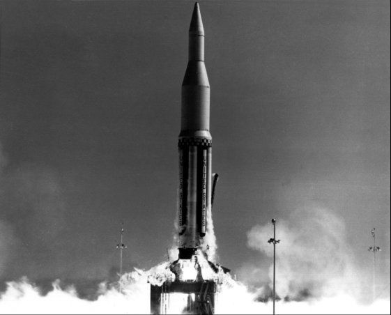
Spectators saw a lake of flame, felt the rush of a shock wave, and then heard the roar of the eight engines. Trailer windows at the viewing site shook in response to the Saturn’s power. Yet for many of the thousands watching the launch, the roar was a letdown. Reporters thought the sound equaled an Atlas launch viewed at half the distance.** The Miami Herald headline the next morning read: “Saturn Blast ‘Quieter’ Than Expected."42
Although the Saturn’s roar failed to meet expectations, the human noise at LC-34’s control center was impressive. Bart Slattery, a NASA information officer, told reporters that when the rocket passed maximum Q (point of greatest aerodynamic pressure) at about 60 seconds into the flight, “all hell broke loose in the blockhouse.” Kurt Debus’s face reflected the happy sense of accomplishment hours later when he informed the press that it had been a nearly perfect launch.43
The success was particularly welcome to the Kennedy administration, coming at a time of high tension between the United States and the Soviet Union. The raising of the Berlin Wall had stunned the Western world in August 1961. President Kennedy had responded with a partial mobilization of U.S. reserve forces, but most political analysts considered the events a Russian victory. In late October, as the Soviet Union prepared to test a 50-megaton H-bomb, the President had proposed a massive fallout shelter program. On the day of the SA-1 launch, Russian tanks moved into East Berlin for the first time in several years.
The space race was an important element in a Cold War that threatened to turn hot. With the success of the Saturn booster, the United States had achieved a launch capability of 5.8 million newtons (1.3 million pounds of thrust). Space reporters were quick to point out the limits of the American success. The Soviet Union already had workable upper stages for their first stage. Furthermore, the current Russian tests in the Pacific would likely result in sizable booster advances. Despite these caveats, commentators agreed that SA-1 was an important step toward a lunar landing.44
- Establishing an exact ratio of RP-1 to LOX was important since simultaneous depletion of propellants at cutoff was desired. Flight data later indicated a 0.4% deviation in the RP-1 fuel density sensing system, 0.15% above design limits. Too much LOX (400 kilograms) and not enough RP-1 (410 kilograms) were therefore loaded. The error contributed to a premature cutoff 1.6 seconds ahead of schedule.
- Marshall Center scientists, after studying readings taken in nearby communities during launch, explained that weather conditions were such that sound was absorbed by the atmosphere. As a result, sound levels were less than those experienced during static firings at Huntsville.
ENDNOTES
- W. R. McMurran, ed., “The Evolution of Electronic Tracking, Optical, Telemetry, and Command Systems at the Kennedy Space Center,” mimeographed paper (KSC, 17 Apr. 1973), fig. 2; MSFC, Saturn SA-1 Flight Evaluation, report MPR-SAT-WF-61-8 (Huntsville, AL, 14 Dec. 1961), p. 235. The Saturn Flight valuation Working Group at MSFC published reports on all the Saturn C-1 launches. See also MSFC, Results of the First Saturn I Launch Vehicle Test Flight, SA-1, report MPR-SAT-64-14 (Huntsville, AL, 27 Apr. 1964) which superseded the above report, and MSFC, Results of the Saturn I Launch Vehicle Test Flights, report MPR-SAT-FE-66-9 (Huntsville, AL, 9 Dec. 1966).X
- MSFC, C-1, C-2 Comparison, pp. 3-7. See pp. 68, 78-82 for Long-Range Program (Sloop Committee Report) of Sept. 1960.X
- Oswald H. Lange, “Saturn Program Review,” 27 Jan. 1961; Akens, Saturn Illustrated Chronology, pp. 13, 19.X
- F. A. Speer, “Saturn I Flight Test Evaluation,” American Institute of Aeronautics and Astronautics paper 64-322 given at Washington, D.C., 29 June-2 July 1964, p. 2; ARINC Research Corp., Reliability Study of Saturn SA-3 Pre-Launch Operations, by Arthur W. Green et al., publication 247-1-399 (Washington, 3 Jan. 1963), pp. 2-21 through 2-23.X
- ABMA, Organizational Manual (Redstone Arsenal, AL, 5 Mar. 1959), Sec. 530, pp. 13-15, copy available in Historical Div., Sec. of General Staff, Army Missile Div., Redstone Arsenal, AL; Russell interview.X
- Moser interview, 30 Mar. 1973.X
- Grady Williams interview.X
- Debus to Joseph Shea, “Principles of Operations of the MSFC Firing Team at Cape Canaveral,” 22 Mar. 1962, Debus papers, KSC Archives.X
- Ibid.X
- Ibid.X
- Debus to Committee for LOD Scheduling and Test Procedures, “Day-by-Day Test Schedule for Saturn SA-1,” 16 Mar. 1961, ibid.; DDJ, 14 Mar. 1961.X
- Moser interview, 30 Mar. 1973; DDJ, 17 Apr. 1961,X
- MSFC, Catalog of Systems Tests for Saturn S-1 Stage, pp. III-46-III-54 (Huntsville, AL, 1 Sept. 1961), Moser papers, Federal Archives and Records Center, East Point, GA, accession 68A1230, boxes 436257, 436259.X
- “Launch Facilities and Support Equipment Office [hereafter cited as LFSEO] Monthly Progress Report,” 12 June 1961, p. 2; “LFSEO Monthly Progress Report,” 13 July 1961, pp. 2-3.X
- DDJ, 11, 12 May 1961; “LFSEO Monthly Progress Report,” 12 June 1961, p. 3.X
- Zeiler to Debus, “Work Statement,” 14 July 1961.X
- “Saturn SA-1 Schedule,” 15 Aug. 1961, Moser papers, Federal Archives and Records Center, East Point, GA, accession 68A1230, boxes 436257, 436259.X
- DDJ, 24 Mar., 26 Apr. 1961; Akens, Saturn Illustrated Chronology, p. 18; Georg von Tiesenhausen, “Ground Equipment to Support the Saturn Vehicle,” paper 1425-60 presented at the 15th annual meeting of the American Rocket Society, Washington, D.C., 5-8 Dec. 1960, pp. 2-3.X
- “LFSEO Monthly Progress Report,” 13 July 1961, p. 4; Akens, Saturn Illustrated Chronology, pp. 21, 26-27.X
- MSFC, SA-1 Vehicle Data Book, pp. 123-30.X
- Karl L. Heimburg to MSFC Dep. Dir. for R & D, “Water Route for NASA Vessels to Cape Canaveral,” 9 Feb. 1962, attached to a response from Debus, 14 Feb. 1962, in Debus papers.X
- MSFC, SA-1 Flight Evaluation, p. 7; Akens, Saturn Illustrated Chronology, p. 26; Crunk interview; Zeiler interview, 23 July 1973; von Tiesenhausen, “Equipment to Support the Saturn,” pp. 2-3.X
- MSFC, SA-1 Flight Evaluation, p. 7; “LOD Daily Journal,” 27 July 1961; “Saturn SA-1 Schedule,” 15 Aug. 1961.X
- MSFC, SA-1 Flight Evaluation, p. 8; MSFC, “Saturn Quarterly Progress Report,” July-Sept. 1961, p. 1; “Saturn Schedule,” 15 Aug. 1961; interviews with Newall, Marsh. and Humphrey.X
- Grady Williams interview.X
- MSFC, SA-1 Vehicle Data Book, pp. 74-81.X
- Interviews with Edwards and Glaser.X
- White interview; MSFC, Consolidated Instrumentation Plan for Saturn Vehicle SA-1, by Ralph T. Gwinn and Kenneth J. Dean, report MTP-LOD-61-36.2a (Huntsville, AL. 25 Oct. 1961).X
- White interview.X
- MSFC, SA-1 Flight Evaluation, p. 7.X
- Moser interview, 30 Mar. 1973.X
- Ibid.; “Saturn SA-1 Schedule,” 15 Aug. 1961; MSFC, SA-1 Flight Evaluation, pp. 8, 200-202.X
- Moser interview, 30 Mar. 1973; “ Saturn SA-1 Schedule"; MSFC, SA-1 Flight Evaluation, pp. 7-9; LOD, “Saturn Test Procedures, SA-1 G & C Overall Test #3,” Moser papers, Federal Archives and Records Center, East Point, GA, accession 68A1230, boxes 436257, 436259.X
- Moser interview, 30 Mar. 1973; “ Saturn SA-1 Schedule"; MSFC, “SA-1 Flight Evaluation,” pp. 8-9; George Alexander, “Telemetry Data Confirms Saturn Success,” Aviation Week and Space Technology, 6 Nov. 1961, pp. 30-32.X
- ” Saturn Test Procedures: SA-1 Mechanical Office L-1 Day Prelaunch Preparations,” Moser papers; MSFC, SA-1 Flight Evaluation, pp. 9-10; interview with Chester Wasileski by Benson, 14 Dec. 1972; Pantoliano interview.X
- MSFC, Launch Countdown Saturn Vehicle SA-1, report MIP-LOD-61-35-2 (Huntsville, AL, 3 Oct. 1961), pp. 9-15, Moser papers.X
- MSFC, SA-1 Flight Evaluation, p. 10; MSFC, Countdown SA-1.X
- MSFC, Countdown SA-1, pp. 20-23.X
- MSFC, SA-1 Flight Evaluation, pp. 11-12; MSFC, Countdown SA-1, pp. 28-30; LOD, Saturn Test Procedures: Set Up LO2 Facility for Fast Fill (T - 100), procedure LOD-M703; LOD, Saturn Test Procedures: Fast Fill LO2 Loading (T - 60), procedure LOD-M704.X
- MSFC, Countdown SA-1, pp. 36-39; Alexander, “Telemetry Confirms Success,” p. 31: “Emergency Procedures SA-1,” LOD Networks Group, pp. 2-3, Moser papers.X
- Richard Austin Smith, “Canaveral, Industry’s Trial by Fire,” Fortune, June 1962. pp. 204, 206; “Saturnalia at Canaveral,” Newsweek, 6 Nov. 1961, p. 64; Miami Herald, 28 Oct. 1961, p. 1; “Saturn’s Success,” Time, 3 Nov. 1961, p. 15.X
- New York Times, 28 Oct. 1961, pp. 1, 9; Miami Herald, 28 Oct. 1961, p. 1. The MSFC news release on the SA-1 launch, dated 1 Nov. 1961, included a paragraph on the sound effect.X
- Miami Herald, 28 Oct. 1961, p. 1 (UPI release).X
- New York Times, 27 Oct. 1961, p. 1; 28 Oct. 1961, pp. 1, 9.X